Configuration Process
The Configuration Process is where you specify exactly how spatial and attribute information is stored in the AutoCAD drawing file in terms of your destination database. The Configurator defines the AutoCAD template and ensures that it meets the needs of published industry standards and individual corporation’s requirements. It provides an intuitive environment for defining corporate data requirements and performs a series of automated checks to assess the validity of configured data rules.
Configurator also provides users the ability to generate and organize the ACDC menu objects for AutoCAD, AutoCAD Map and BricsCAD. The Menu Mode incorporates some of the CUI commands into the Configuration Pane to allow users to have access to create menu groups, create and manage menu items and change the order in which the menu items appear in the menus.
The Configuration process involves defining:
- The location of the destination database.
- Where each object in the drawing is to be written in the destination database.
- Exactly where to find the attribute information for each object in the drawing.
- The required data format of each attribute value.
- The geometric requirements of the data (snapping, breaking, networking).
- Allow users to configure, preview and create their own ACDC menu content and layout.
These definitions form the basis of the validation rules used in the Validation Process Validating DWG File.
Configurator Mode
When launching Configurator from the ACDC menu, it defaults to display the Configuration Mode and loads the ACDC Configuration components in the Tree Pane. Selecting the Edit ACDC menu layout configuration button  will switch the Configuration screen to Menu Mode and load the ACDC Menu components in the tree pane. Conversely, if in Menu Mode, selecting the Edit ACDC configuration button
  will switch the Configuration screen back to Configurator Mode.
Configuration Mode enables the Administrator to capture and configure ACDC validation rules and settings that are used by the ‘Validator’ to validate the drawing. Menu Mode enables the Administrator to add or remove Menu Groups and manage menu items within the Menu Groups.
Configurator Buttons
Below is an explanation of the functionality of the buttons on the Configuration screen when in Configurator Mode.
 Edit ACDC menu layout configuration: Switches the Configurator to Menu Mode to enable menu layout edits.
 Verify configuration: This tool runs a selection of checks on your configuration to assess its validity.
 Clear verification results: Clears the tick and cross graphics from the left tree view pane that are created when the Verify Configuration tool is run.
 Add new record: Adds a record to the selected node/tab.
 Delete selected records: Deletes the record currently selected in the top right grid view pane.
 Preview menu layout: Displays a preview of the menu layout.
 Generate menu: Generates the menu layout and allows the user to save as a .mnu file.
 Refresh data: Refreshes the Configurator pane with the data stored in the ACDC system tables. It also refreshes the left tree view pane with all the configured blocks.
Connect to ACDC Database
To commence the configuration process, you must be connected to the database that contains the ACDC system tables (WAE tables). To do this, complete the following steps:
- Run ACDC by double clicking the desktop icon.
- Once the applicable AutoCAD product opens, press the Connect to Database button
 from the ACDC Toolbar. This will open the Connect to Database dialog.
 - In the Connect to Database dialog, enter connection details for the database that contains the ACDC system tables. A completed login dialog should resemble the following:
NOTE: The Database Type offers both Oracle or SQL Server connection types. Ask your Administrator for your connection and login details.

Check the tick-box next to Windows Authentication if you are using Single Sign On (SSO)

Fig: Connect to Database Dialog Box. - Once you have finished entering the database details, press the Connect button.
Once the connection is established to the database, you will see a Connected successfully message on the AutoCAD command line. This connection is required to run any of the ACDC tools since it looks at the database tables for the stored configurations.
To view the current connection details at any time, press the Connect to Database button  . This will display the connection details on the AutoCAD command line.
To disconnect from the database, simply press the Disconnect from Database button  . This will terminate any existing database connection that has been established by ACDC.
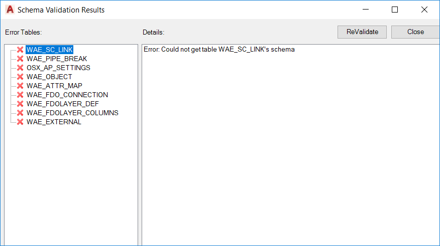
Fig: The Schema Validation Results dialog box.
Save FDO Connections (Does Not Apply to Munsys Users)
This section of the manual does not apply to Munsys users. The following steps describe how to establish the FDO connections to the destination layers.
- Open the AutoCAD Task Pane by typing the MAPWSPACE command on the Command Line and selecting On option.
- Press the Manage Data Content
 button on the Task Pane and select Connect to Data. This will open the Data Connect dialog.
 - In the Data Connect dialog select the applicable connection type (Oracle, MySQL etc.) and complete the Connection name and Service name fields.
Press the Login button.
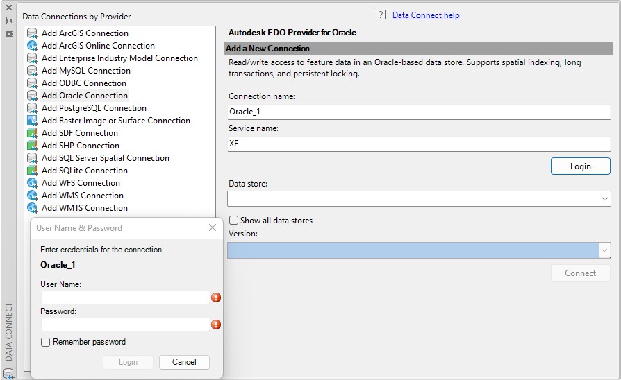
Fig: Adding a New Data Connection - Enter your user name and password in the dialog that appears and press Login.
- Select the desired data store from the Data store drop-down and press the Connect button, ensuring that the Show all data stores box is ticked.
- Tick the check boxes next to the layers you wish to add data to and press the Add to Map button. This will add the selected layers to the Task Pane. You can now close the Data Connect dialog.
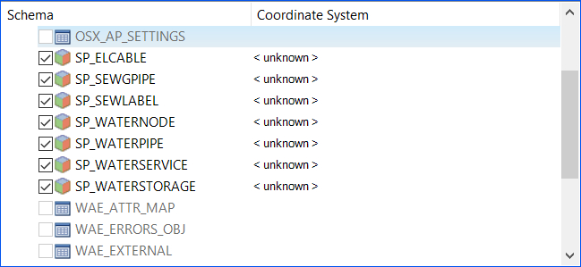
Fig: Adding Selected Layers to Map - With the required destination layers in the Task Pane, press the Save GIS Layer Configuration button
 on the ACDC Toolbar. This will save the data layer connections present in the Task Pane to your ACDC configuration.
 - You will be presented with the Save GIS Layer Configuration Connections dialog box which is populated with a list of GIS layers if they already exist in your ACDC configuration.
- There are two radio buttons available for selection, namely:
- Keep existing: This is the default option and the properties associated to the FDO layers will be kept as previously defined. Select OK.
- Replace existing: If this option is selected, any changes made to the FDO Layer will overwrite those defined in the database. Select OK.
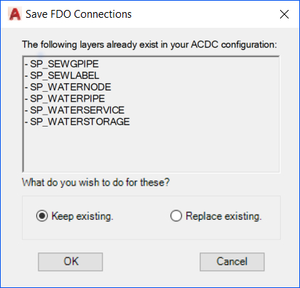
Fig: Save FDO Connections - It is important that this process is done for ALL the required destination layers as this defines the destination layers that you can map your data to.
- The saved connections can be reviewed using the FDO Connections node of the Configurator.
Initial Configurator Settings Review
- Start the ACDC Configurator
 and select the Settings node in the left tree view pane.
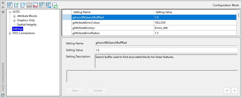
Fig: Settings in the ACDC Configurator - Although default values are assigned to each Configurator Setting when the database is originally created, it is recommended that the following Configurator Settings be reviewed and defined specifically for your project before the Configuration of the Attribute Blocks can commence:
- gCommonBlkName: Common Block used for attributes.
- gDateFormat: Preferred date format DD/MM/YYYY or MM/DD/YYYY.
- gDrawingUnits: Preferred Drawing Units. Meters or Feet.
- gGISType: Select either Feature Data Objects (FDO) or Munsys (must log out/log in for any change to this setting to take affect).
- gLookupFilter: Query filter used to find lookup tables.
- gMaxXExtent, gMaxYExtent, gMinXExtent, gMinYExtent : Database Extents of Project Area.
- gProjection: Expected Projection for projects.
- gProjectionAttribute: Defined Projection Attribute in Common Block.
- gVersion: Database Schema Version.
- gVerifyRealSize: (See section CONFIGURING ‘gVerifyRealValues for SQL Server only).
- gExternalActive: Export data to CSV Files (True or False).
The following Tolerance Settings can also be checked and modified where applicable:
- gLinearChkTol: Tolerance used to flag linear object end points as errors if they are within this tolerance and fall outside of the defined gLinearSnapTol setting.
- gLinearSearchBuffRad: Search buffer used by linear objects to detect nearby linear objects to snap to.
- gLinearShortTol: Shortest linear length allowed.
- gLinearSnapTol: If linear objects are within this distance then they are automatically snapped together.
- gNodeSearchBuffRad: Search buffer used by node objects to detect nearby objects.
- gNodeSnapTol: If a node is within this distance of a linear object it is automatically snapped to that linear object.
- gPipeLengthBreakTol: Minimum allowable length of pipe to be created by a ‘break’ operation.
- gPipeSearchBuffRad: Search buffer used by blocks insertion points to detect pipes to snap to.
- gSCtoPipeSearchBuffRad: Search buffer used to find pipes to which a service connection should be attached.
When logging onto an ACDC schema, the default Symbol path of Meters will be updated to either Feet or Meters based on the gDrawingUnits setting. As part of the validation process, if the drawing being validated has the DWGUNITS set to Meters and the configuration gDrawingUnits setting is set to Feet, the following warning message will be displayed in the command line Warning: Drawing Units does not match setting (Feet), and an entry will be written to the log file with the following description Drawing units does not match setting (Feet).
Conversely, if the drawing being validated has the DWGUNITS set to Feet and the configuration gDrawingUnits setting is set to Meters, the following warning message will be displayed in the command line Warning: Drawing Units does not match setting (Meters), and an entry will be written to the log file with the following description Drawing units does not match setting (Meters).
The gNodeSearchBuffRad setting value can be increased/decreased based on the users needs, as it controls the distance/tolerance between objects of a block. If this setting is changed to anything below 0.2 i.e. 0.1 then an isolated block error will be displayed when an attribute block is placed on the arc section of a polyline..
As part of the initial Configurator Settings, the gProjection and gProjectionAttribute values must be set correctly. The gProjection uses the Drawing Projection set using the AutoCAD Map command mapcsassign, while the gProjectionAttribute value is set to INACTIVE by default and must be updated in the Common Block ORIGIN variable.
As part of the validation process, checks are done to ensure the drawing coordinate system assigned in the TEMPLATE using the AutoCAD Map command mapcsassign matches the Projection assigned in the Common Block ORIGIN attribute..
If no Projection has been assigned in the drawing Template the validation will not be failed, and the resultant validation log file will be updated with a warning message indicating that No Projection has been assigned to the drawing.
If there is a difference between the drawing Template projection and the Common Block Projection, the validation will not be failed, and the resultant validation log file will be updated with a warning message indicating that the Drawing Projection does not match the Projection setting for the Common Block.
These settings are defined within the OSX_AP_SETTINGS database table. Refer to the Configurator Settings section of this manual for more information about these specific settings.
- If you are required to change the value of any of the above settings from their default values, Editing mode will automatically be enabled. You will need to either save or cancel/discard any changes you make.
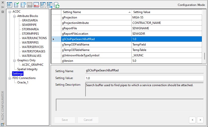
Fig: Editing in the ACDC Configurator
Attribute Blocks
Attribute Blocks – Object Tab
The work carried out in the Attribute Blocks Object tab of the Configurator defines for ACDC exactly how each of your assets are stored in the drawing. This information is used by the Converter to locate and correctly classify each of your assets. This information will be verified at a later stage of the configuration process.
- To begin the configuration process, start the ACDC Configurator
 and select the Attribute Blocks node in the left tree view pane.
 - Select the Object tab.
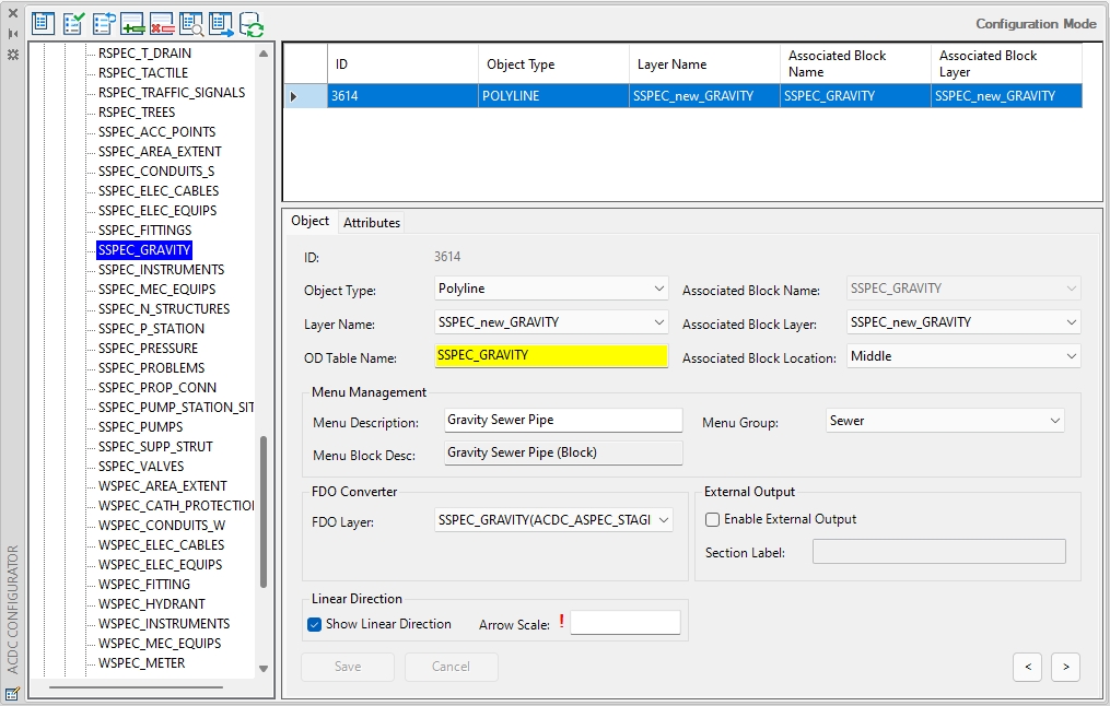
Fig: Attribute Blocks in the ACDC Configurator - To begin configuring your drawing, press the Add new record button
 located at the top of the Configurator dialog. This will add a new record to the Object tab.
 - You must now make selections for each of the attributes specified in the bottom right pane of the Configurator. An explanation of each attribute is as follows:
- Object Type: The AutoCAD object type that is used to represent the asset. Select from the drop-down menu. The Object Type can be:
- Block: If the asset is represented by a node / point entity. For example, a water hydrant.
- Circle: If the asset is represented by a circle. For example, a water reservoir such as a water tank.
- Polygon: If the asset is represented by a polygon. For example, a water reservoir such as a dam.
- Polyline: If the asset is represented as a line entity with two or more series of lines or line segments. For example, a water pipe that consists of multiple line segments.
- Layer Name: The layer on which the objects exist on in your drawing file.
NOTE: In an as-built drawing, each layer cannot contain more than one identical Object Type except for Object Type Block/INSERT. For example, the layer WPIPE can only contain one entry in the Configurator for an Object Type Polyline but no other entries of Object Type Polyline can be recorded for the WPIPE layer even if it has a different associated block. The exception is that a layer of Object Type Block/INSERT can contain more than one record for the same Object Type. See example in the Associated Block Layer description.
- OD Table Name: The object data table that will be created in the validation process to store the configured attributes for the selected object. By default it will receive the associated block name. While it is strongly recommended to leave this at its default value, the OD Table Name must be less than 25 characters and cannot include any spaces. Please rename appropriately (if required).
- Associated Block Name: The block that contains the attributes for the object.
- Associated Block Layer: The layer that contains the associated blocks for the object. The layer is automatically populated for objects of type Block.
NOTE: For objects of type Block, a layer can have more than one associated block. For example, the layer name Valves could be associated with blocks Gate Valve, Scour Valve, or Pressure Release Value (i.e. if the user did not want to create 3 separate layers for each value type). - Associated Block Location: The location at which the associated block is located on the object (is automatically populated for objects of type ‘Block’). The snapping possibilities will vary depending on the object. Choose from the below options:
- Start: If the block has been snapped to the start of the object. (Object Type = Polyline).
- End: If the block has been snapped to the end of the object. (Object Type = Polyline).
- Start or End: If the block has been snapped to the start or end of the object. (Object Type = Polyline).
- Middle: If the block has been snapped to the middle or a middle segment of the object. For a Polyline, the middle can be the midpoint between any vertexes along the Polyline (but not on a vertex). (Object Type = Polyline).
- Inside: If the object is represented by a circle or closed polyline the block must be located inside the object. (Object Type = Circle or Polygon).
- Menu Description: The menu description as displayed in ACDC Configurator.
- Menu Group: The name of the Menu Group to which the block item has been assigned. Select the group from the available drop-down list. If the Menu Group is nested below a Parent Menu Group, the Parent Menu Group and the nested Menu Group is displayed i.e. Water/Water Nodes.
- Menu Block Desc: The description of the block as displayed on the Menu bar.
- FDO Layer: The layer in your Oracle/MS SQL Server database to which the selected object is to be written.
- Munsys Table: (For Munsys users only). The layer in your Munsys Server database to which the selected object is to be written.
- Type Definition: (For Munsys users only). Select the Munsys Object Type.
- Enable External Output (check box): Ticking the box with activate/deactivate the exporting of attributes to CSV/Table. The first column in the CSV/Table file created by ACDC is named SECTION_LABEL. The value that will be written to this column for the current object is automatically defined here in the Section Label field. The file type, name and location are specified by the gExternalOutputTarget, gExternalFile and gExternalFileLocation settings respectively.
- Show Linear Direction: This is a setting used to toggle the display of linear direction arrows on those objects selected in the validation process (YES/NO). If the tick-box is checked, the arrows will display on the configured polyline objects.

Fig: Linear Direction Settings set On
NOTE: Linear direction refers to the direction in which the polyline has been drawn in the CAD drawing. This is not to be confused with the flow direction which is validated using the attribute values captured for both the start and end invert levels. - Arrow Scale: This setting sets the scale of the arrow to be displayed on the objects indicating linear direction. This setting uses the Drawing Units (gDrawingUnits) to determine which folder to use to locate the symbol darrow.dwg, and display in either Feet or Meters.

Fig: Linear Direction Arrow Scale Settings
- Object Type: The AutoCAD object type that is used to represent the asset. Select from the drop-down menu. The Object Type can be:
- Once you have populated each of the attributes, press the Save button. This will add the record to the top right grid view pane. A completed record will typically resemble the below:
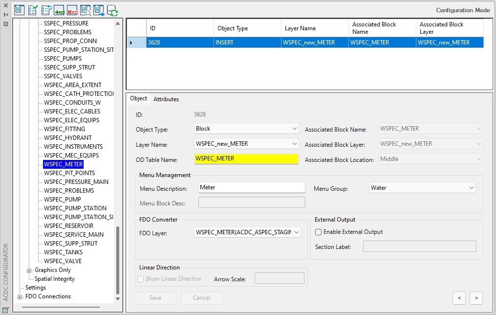
Fig: Linear Direction Settings set On
- You must complete this process for each of the assets/object types you wish to convert in your drawing file.
- Press the Refresh button
 located at the top of the Configurator dialog to update the left tree view with your defined assets.
Attribute Blocks – Attributes Tab
The information stored in the Attributes tab is used to tell the Converter which attributes to store against each asset, and exactly where to find these attributes.
CAD Blocks, made up of a collection of geometries, can be placed to represent asset information in a CAD drawing. CAD symbols are often used to portray assets with a single X;Y;Z point location such as a Sanitary Sewer Manhole, and block attributes are captured to describe the asset’s properties and store information relating to the asset. So a single Block object may have many attributes configured, including reference to the Common Block attributes.
In the example of using a block to represent a Sanitary Sewer Manhole, as part of the block definition you could setup a circle symbol (dwg file) to represent the manhole, define the base insertion point at the center of the circle to place the manhole on a line object to represent a pipe, and setup attributes to describe the properties of the manhole, such as the manhole reference number, depth, cover level, material, location, comments etc.
As per block attribute definitions in AutoCAD, each individual attribute describing an asset property has a unique tag name with a tag prompt/description to advise what information is required for capture. The Block Configuration enables users to define block attribute tags by capturing a Tag description/prompt, assign default values where applicable and set the Tag mode in terms of the tag being visible or not.
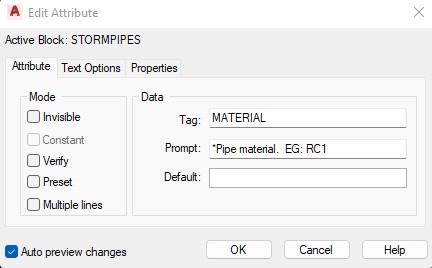
Fig: Editing CAD Block Attributes
The entire configuration can now be stored in the ACDC database, and using SQL Scripts, the blocks can be generated using this attribute information.
The steps detailed below indicate how to define the attributes to store against each of the asset/object type combinations defined in the Object tab.
- Select a record in the Object tab of the Attribute Blocks node. This will be the asset against which you will define attributes.
- Select the Attributes tab.
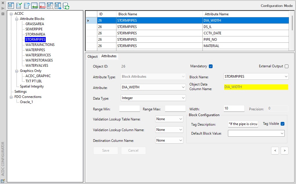
Fig: The Attributes Tab
- Press the Add new record button
 to begin defining an attribute. Once you press this button, a blank row will be added to the top-right grid view pane and the bottom-right pane will become a form, which is used to define the details of the attribute.
NOTE: The Object ID value will be the same as the selected ID value for the objected selected on the Object pane. This ID is used to link the attributes to object in the database. - You must now populate each of the fields in the bottom right pane of the ‘Configurator’. An explanation of each is as follows:
- Mandatory (check box): Defines if the attribute is required. If this is checked, any objects of the defined type that contain blank/null values for this attribute will be flagged as errors. If the block is generated using the SQL Scripts, an * will automatically be appended to the start of the Tag Description indicating to the data capturer that the attribute is a mandatory field.
- External Output (check box): If this is checked, the attribute value will also be written to a separate CSV/or Table file during the Conversion process.
NOTE: Attributes will only be exported if the Enable External Attributes check box in the Object tab is also ticked.The file type, name and location are specified by the gExternalOutputTarget, gExternalFile and gExternalFileLocation settings respectively. - Attribute Type: Defines the source of the attribute value. The available options are:
- Block Attributes: The attribute value is currently held in a block in the drawing.
- Database Sequences: The attribute value will be supplied by a database sequence (for Oracle users).
- Database Functions: The attribute value will be supplied by a database function.
- Database Procedures: The attribute value will be supplied by a database procedure (for MS SQL Server users).
- Object Attributes: The attribute value will be determined from the geometry of the object (for example, length, rotation, area, circumference).
- Block Name: The name of the block that contains the value for this attribute. This is only applicable to attributes of type Block Attributes.
- Attribute: The name of the block attribute/database sequence/database function/object geometry/ object location property to use to populate this attribute value.
- Object Data Column Name: This value is populated with the name of the column in the object data table that will store this attribute based on the selection of the Attribute above. While it is strongly recommended to leave this at its default value, the name must be less than 25 characters and cannot include any spaces. Please rename appropriately (if required).
- Data Type: The data type that will be used to store the attribute. Choose from Character, Real, Integer or Date.
- For Character specify:
- Max Length: The maximum length that the attribute value can be in the Width setting.
- For Real or Integer specify:
- Width: The maximum allowed number of whole number digits. For Real this will be the maximum number of digits appearing before the decimal place. For example, a Width of 4 would cater for numbers with 4 or less whole digits, such as 10, 1000 but not 10000.
- Precision (for Real only): This is the maximum allowed number of digits appearing after the decimal place. For Data Type Integer the Precision field will be greyed out and set to 0. For example, a Width = 4 and Precision = 2 would cater for numeric digits such as 10.824 and 1000.643423545 which would be truncated to 10.82 and 1000.64 respectively.
- Range Min: The minimum numeric value allowed for this field.
- Range Max: The maximum numeric value allowed for this field.
- For Date specify:
- Min Date: The minimum permissible date in the format as specified in Configurator settings.
- Max Date: The maximum permissible date in the format as specified in Configurator settings.
- For Character specify:
- Validation Lookup Table Name: The lookup table that contains a list of predefined values for this attribute.
- Validation Lookup Column Name: The column in the selected validation lookup table that contains the actual attribute value to be stored.
- Destination Column Name: The column in your destination layer where this attribute value is to be placed.
- Tag Description: Block Attribute description / prompt.
- Default Block Value: The Asset Owner can assign a default value which will be applied to all blocks captured. The default value can be updated using Block Editor on placement of the block in the drawing.
NOTE: A good example of assigning a Default Block Value would be if you had an Asset Owner attribute where all assets belonged to the same organisation. To prevent the data capturer from having to capture the same Asset Owner details repeatedly for each placement of the same type of asset, the default Asset Owner can be defined in the Attributes configuration, and updated at the point of capture where there is an exception, rather than the norm. - Tag Visible: Determines if the tag description (prompt) is displayed or not when capturing or editing attributes.
NOTE: As you are completing this form, make sure you consider each option carefully. The selections made here determine the nature of the rules used to validate the drawing and they define exactly how the final data is to be stored.
- Press the Save button once you have completed the form for the new attribute. Repeat this process for all of the attributes that are to be stored against the current object.
To add a new record, complete the following steps:
- In the Attributes tab, add a new record by pressing the Add new record button
 .
. - Complete the new attribute details as follows:
- Attribute Type:
- Database Function (for MS SQL Server users)
- Database Sequence (for Oracle users)
The Database Sequence is the predefined database sequence/function that is installed with the ACDC system tables. Its purpose is to create a unique numeric number for each record that is to be transferred to the defined destination tables.
- Data Type: Integer.
- Destination Layer Column Name: Select the applicable ‘ID’ column for the destination table.
- Attribute Type:
- Press the Save button to store the new attribute definition in the database.
Duplicate Record and Copy Attributes
When an asset can be represented by both blocks and polygons, a separate record must be defined for each of these object types. The ‘Configurator’ contains a tool to facilitate this process, the Duplicate Record and Copy Attributes tool. This tool duplicates the selected record with the associated attribute values and allows you to edit the AutoCAD object type you require.
To use this tool, refer to the steps below:
- In the top right grid view pane, select the record you wish to duplicate.
- Right-click on this record and select Duplicate Record and Copy Attributes from the context menu that appears.
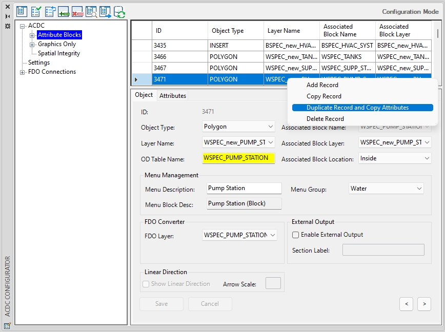
Fig: Duplicating Records in the Configurator - A new record will be created with all the fields set to the same values as those of the record you selected to duplicate. The user will only have access to Object Tab to change the Object Type field, after which the record must first be saved to edit any further Attribute values.
Press the Save button once you have selected the required Object Type to save the record. - The results of this duplication process is shown in the figure below. After duplication, two records for the pump station assets exist – one for those represented by block, and another for those represented by polygons.
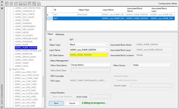
Fig: Duplicate Record in the ACDC Configurator
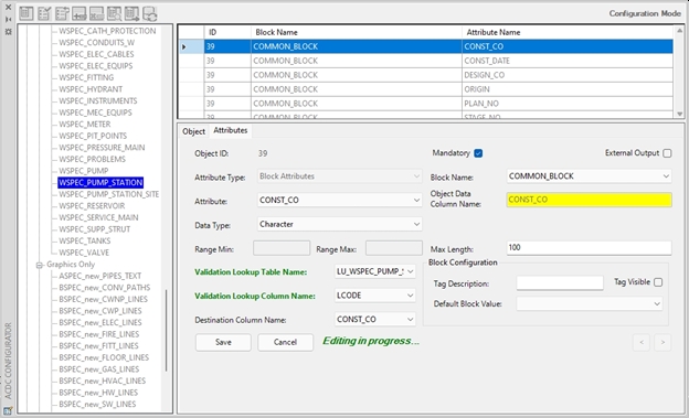
Fig: Editing Duplicate Record Attributes
Graphics Only
Graphics Only – Object Tab
Graphics Only blocks are typically where only the line work is required to represent an asset without any associated attribute information being captured. However, there may be instances where the Asset Owner may assign attributes to the block, but the data capturer is not prompted to add attributes. An example of this scenario would be if the Asset Owner were to add an attribute based on a sequence and the sequence number is assigned automatically when the asset is placed in the drawing.
The Objects tab of the Graphics Only node is where you define the layers that contain no attribute data, and to which layers these graphics connections can be connected. Select the Graphics Only node in the left tree view pane.
- Select the Object tab in the bottom right pane.
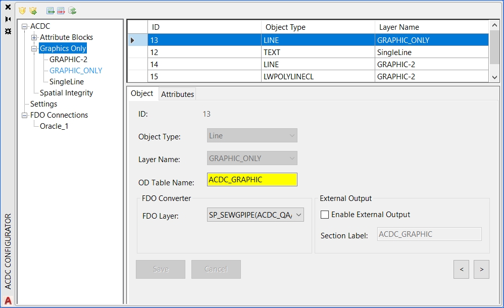
Fig: Object Tab for Graphics Only
- To begin configuring your drawing, press the Add new record button
 located at the top of the Configurator dialog. This will add a new record to the Object tab.
 - You must now make selections for each of the attributes specified in the bottom right pane of the Configurator. An explanation of each attribute is as follows:
- Object Type: The AutoCAD object type that is used to represent the asset. Select from the drop-down menu. The Object Type can be:
- Block: If the asset is represented as a block entity. For example, a Survey Point.
- Circle: If the asset is represented by a circle. For example, a water reservoir such as a tank.
- Polygon: If the asset forms a polygon. For example, a Water reservoir such as a dam.
- Polyline: If the asset is represented as a line entity with two or more series of lines or line segments. For example, a water pipe that consists of multiple line segments.
- Single Line Text: or text within a drawing that needs to be displayed. For example, construction notes.
NOTE: Single Line Text objects do not have associated blocks.
- Layer Name: The layer that the objects exist on in your drawing file.
- Menu Description: The menu description as displayed in ACDC Configurator.
- Menu Group: The name of the Menu Group to which the block item has been assigned. Select the group from the available drop-down list.
- Menu Block Description: The description of the block as displayed in the Menu bar.
- OD Table Name: The object data table that will be created in the validation process to store the configured attributes for the selected object. By default it will receive the associated block name. While it is strongly recommended to leave this at its default value, the OD Table Name must be less than 25 characters and cannot include any spaces. Please rename appropriately (if required).
- FDO Layer: The layer in your Oracle/MS SQL Server database to which the selected object is to be written.
- Enable External Output (check box): Ticking the box with activate/deactivate the exporting of attributes to CSV/Table. The first column in the CSV/Table file created by ACDC is named SECTION_LABEL. The value that will be written to this column for the current object is automatically defined here in the Section Label field. The file type, name and location are specified by the gExternalOutputTarget, gExternalFile and gExternalFileLocation settings respectively.
- Object Type: The AutoCAD object type that is used to represent the asset. Select from the drop-down menu. The Object Type can be:
- Once you have populated each of the attributes, press the Save button. This will add the record to the top right grid view pane.
Graphics Only – Attribute Tab
The Attributes tab for a Graphics Only block is typically only used when there are default attributes assigned such as Database Sequences or Database Functions. An example of this is where the Asset Owner were to add an Attribute based on a Database Sequence and the next available sequence number is assigned automatically from the database when the asset is placed in the drawing. In this scenario the user is not prompted to capture any attributes.
The following Attribute settings would typically be defined for Database Sequence type attributes for Graphics only Blocks:
- Mandatory: By default this is checked as being mandatory, and should remain checked for this scenario.
- Attribute Type: Set to Database Sequence.
- Sequence: Select the appropriate sequence from the drop-down which is populated based on the connection to the database.
- Data Type: The data type that will be used to store the attribute. In this scenario for a sequence value, it would most likely be set to Integer.
- Width: The maximum allowed number of whole number digits. For Real this will be the maximum number of digits appearing before the decimal place. For example, a Width of 4 would cater for numbers with 4 or less whole digits, such as 10, 1000 but not 10000.
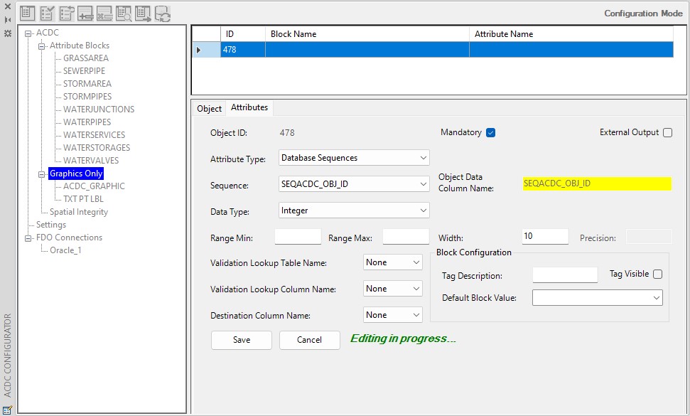
Fig: Database Sequence for Graphics Only Attributes
Spatial Integrity
Spatial Integrity – Linear Branch Tab
The Linear Branch tab of the Spatial Integrity node is where you define the layers that contain service connections, and to which layers these service connections can be connected.
- Select the Spatial Integrity node in the left tree view pane.
- Select the Linear Branch tab in the bottom right pane.
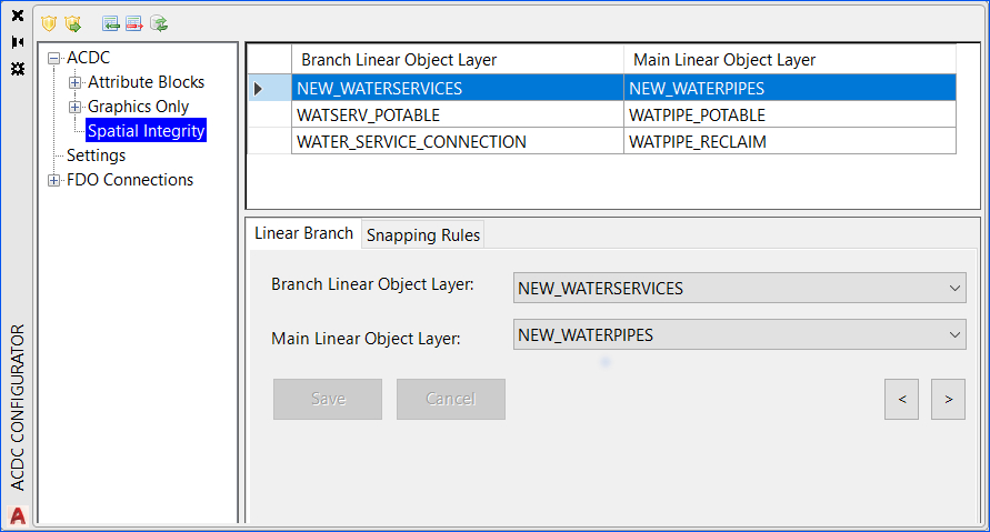
Fig: Linear Branch Tab for Spatial Integrity
- To begin defining linear associations for service connections, press the Add new record button
 . This will add a new blank record to the top right grid-view pane and two drop-down controls will appear in the bottom-right pane.
 - Select the layer that contains service connections in the Branch Linear Object Layer drop-down.
- In the Main Linear Object Layer drop-down, select the layer that contains objects to which the service connections can be connected.
- Press Save to save this rule. A new record will appear in the top-right grid view pane.
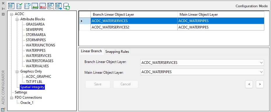
Fig: Linear Branch Options
- Add a new record for each of the different branch/main linear object layer combinations.
Spatial Integrity – Snapping Rules Tab
The Snapping Rules tab of the Spatial Integrity node node is where you define the snapping behavior for nodes (blocks) to linear objects. Nodes that fall within the gNodeSnapTol setting will be snapped as defined here.
- Select the Spatial Integrity node, then select the Snapping Rules tab.
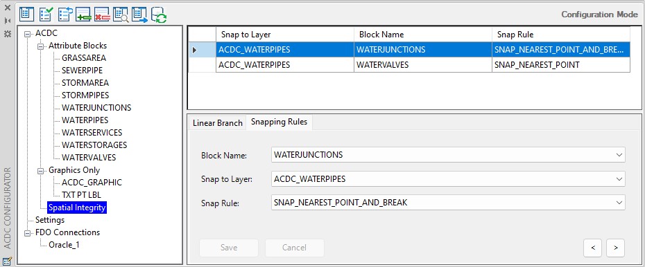
Fig: X
- To define a new snapping rule, right-click and select the Add new record button
 . This will add a new blank record to the top right grid-view pane and a series of blank drop-downs in the bottom right pane. You must populate each of these drop-downs to define a snapping rule. A definition of each of the drop-downs is as follows:
- Block Name: The name of the block you want snapped.
- Snap to Layer: The name of the layer that contains the linear objects you want the selected blocks to snap to.
- Snap Rule:: The snapping behavior. The options for this are.
- SNAP_NEAREST_END: This will snap the defined blocks to end points of linear objects in the selected layer.
- SNAP_NEAREST_POINT: This will snap the defined blocks to the nearest linear object within the selected layer.
- SNAP_NEAREST_POINT_AND_BREAK: This will snap the defined blocks to the nearest linear object within the selected layer, and break the linear object at the snapping location.
- Press Save once you have made the required selections in the drop-downs. This will populate the fields of the new record in the top right grid-view pane.
- Repeat this process for all the different node to linear object snapping combinations you require.
Verify Configuration
The Verify configuration tool checks for inconsistencies in the configuration. The list of specific checks that this tool performs is located in Verify Configuration Test Details. You must complete this process before continuing on to the Validate ACDC Drawing process.
Before this verification can be run, the user must be connected to the database, they must have loaded the drawing to be validated since some of the verification checks are against layers and blocks which must exist in the drawing, and the user must have opened the Configurator dialog box.
To run the Verify configuration tool open the drawing that is to be verified complete the steps below.
- Press the Verify configuration button located on the Configurator dialog. This will display the Verify configuration dialog.
- The Verify configuration dialog will display (Depending on your requirement, select the Comprehensive Check box. See Verify Configuration Test Details.
- On the Verify configuration dialog, press the Start button. Once Verify configuration has begun the user can stop the checks by clicking the Stop button. However the Verify configuration check will cease without being completed.
- A series of configuration checks will be performed and the results are displayed in the dialog. The test log is split into sections based on the ACDC systems tables that are being checked. Scroll down the results text box to view the test details. Tests that have Check Successful have passed. Tests that fail will contain Check Failed followed by a description of the error and a list of the specific objects that violate the check.
- Monitor the Progress bar to see when the check is complete.
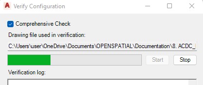
Fig: Verify Configuration progress bar
- If you wish to save the results to a text file, press the Save to file button.
- Close the Verify configuration dialog, by pressing the Close button.
- The results of the Verify configuration process are displayed graphically in the left tree view pane of the Configurator by a series of ticks
 (success), exclamation marks
  (warnings) and crosses
  (errors). All items that have warnings and errors must be addressed before proceeding to the Validation Process.
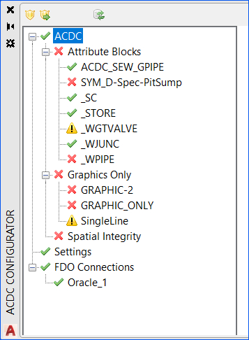
Fig: Verify Configuration Tree View
- To investigate an error/warning, select an item with a red cross (error)
 or exclamation mark (warning)
  in the left tree view pane.
 - In the top left of the Object tab grid-view pane, erroneous records that have failed the Verify configuration are flagged by the red cross symbol
 . These will need to be addressed. Warning messages
  should also be investigated. You may have to switch tabs in the bottom right window to find the records containing errors/warnings. If you hover your cursor over the symbol in the grid view pane you will be given a description of the error/warning.
In the example below, the configured record is not assigned with a valid destination column name. This is not allowed, so its flagged as an error and must be addressed.

Fig: Configured Record with an invalid destination Column Name
- Correct all of the errors as required.
- Once you have addressed all the detected errors, press the Clear verification results button
 located in the top left corner of the Configurator dialog. This will clear the Verify configuration results graphics from the Configurator.
 - Re-run the Verify configuration tool. If no red crosses are generated in the left tree view pane, you can move on to the Validation Process.
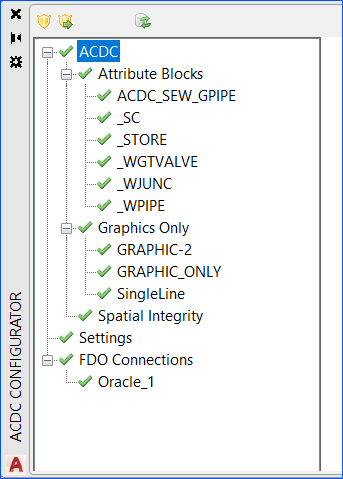
Fig: Successful Verify Configuration Tree View
Verify Configuration Test Details
The Verify Configuration tool performs a series of tests on the configuration and the currently open drawing file. The Comprehensive Check box exists to allow additional checking of data types and formats such as width, precision and max length against the destination table. If working with data types that use these parameters, it is a good idea to check the box as it will detect if the data format of an attribute can be written to the FDO data source. This option can slow the verification check. An explanation of each of the tests performed by the Verify Configuration tool is listed below. The test details below are listed in the same order as in the Verify Configuration log file.
Configurator Settings
Table 1- Validating OSX_AP_SETTING Table
The tests in this section verify the settings you specified in the Settings node of the Configurator.
| Check No. | Description |
| 1.1 | This check verifies that all the saved settings values are valid. |
Table 2- Validating WAE_OBJECT Table
This section refers to checks carried out on the records you created in the Object tab of the Attribute Blocks node.
| Check No. | Description |
| 2.1 | General Description: Tests that features defined in the ‘Object’ tab have had attributes created for them in the ‘Attributes’ tab. Technical Description: Checks that ID values in WAE_OBJECT exist as FK_ID values in WAE_ATTR_MAP. |
| 2.2 | General Description: Tests that features defined in the ‘Object’ tab have had blocks created for them in the ‘Attributes’ tab. Technical Description: Checks that ASSOC_BLOCK_NAME values in WAE_OBJECT exist as BLOCK_NAME values in WAE_ATTR_MAP. |
| 2.3 | General Description: Checks that blocks referred to in the ‘Object’ tab exist in the currently open drawing. Technical Description: Checks ASSOC_BLOCK_NAME values in WAE_OBJECT exist in the currently open drawing. |
| 2.4 | General Description: Checks that layers selected in the ‘Layer Name’ drop-down in the ‘Object’ tab exist in the currently open drawing. Technical Description: Checks ACDC_LAYER values in WAE_OBJECT exist in the currently open drawing. |
| 2.5 | General Description: Checks that layers selected in the ‘Associated Block Layer’ drop-down in the ‘Object’ tab exist in the currently open drawing. Technical Description: Checks ASSOC_BLOCK_LAYER values in WAE_OBJECT exist in the currently open drawing. |
| 2.6 | General Description: Checks that records in the ‘Object’ tab that you used the ‘Duplicate’ tool on have the same ‘OD Table Name’ value. Technical Description: In WAE_OBJECT, this test checks that records with the same ID value also have the same OD_TABLE_NAME value. |
| 2.7 | General Description: Checks that each ‘OD Table Name’ has been assigned to only one object. Technical Description: Checks that each OD_TABLE_NAME value has only one corresponding ID value (unique). |
| 2.8 | General Description: Checks that each ‘OD Table Name’ does not contain any space characters. Technical Description: Checks that each OD_TABLE_NAME value does not contain space character (unique). |
| 2.9 | General Description: Verifying Object Type in WAE_OBJECT.ACAD_OBJECT_TYPE. Technical Description: The purpose is to check if the column value of ACAD_OBJECT_TYPE is correct or not. |
| 2.10 | General Description: Verifying FDO layer geometry types against WAE_OBJECT.ACAD_OBJECT_TYPE. Technical Description: The purpose is to check if the FDO layer’s geometry type is compatible with ACAD_OBJECT_TYPE (such as if FDO layer’s geometry is POLYGON while ACAD_OBJECT_TYPE is POLYLINE, they are incompatible). |
Table 3- Validating WAE_ATTR_MAP Table
This section refers to checks carried out on the records you created in the Attributes tab of the Attribute Blocks node. Check number 3.10 is only run when the Comprehensive Check box is checked on the Verify configuration dialog.
| Check No. | Description |
| 3.1 | General Description: Checks that attributes defined in the ‘Attributes’ tab are referenced to an existing object in the ‘Object’ tab. Technical Description: Checks that FK_ID values in WAE_ATTR_MAP table have matching ID values in WAE_OBJECT table. |
| 3.2 | General Description: For attributes defined as type ‘Block Attributes’ in the ‘Attributes’ tab, this check verifies that blocks exist in the currently open drawing file that actually contain the defined attributes. Technical Description: BLOCK_NAME/TAG_NAME combinations in the WAE_ATTR_MAP table exist in the currently open drawing. This only applies where TAG_TYPE = BLOCK. |
| 3.3 | General Description: Checks that database sequences referenced in the ‘Attributes’ tab exist is the ACDC database/schema. Technical Description: For records in WAE_ATTR_MAP where TAG_TYPE = SEQUENCE, the associated TAG_NAME value exists as a sequence in the ACDC database/schema. |
| 3.4 | General Description: Checks that database functions referenced in the ‘Attributes’ tab exist is the ACDC database/schema. Technical Description: For records in WAE_ATTR_MAP where TAG_TYPE = FUNCTION, the associated TAG_NAME value exists as a function or stored procedure that does not accept any input variables in the ACDC database/schema. |
| 3.5 | General Description: For attributes of type ‘Block Attributes’, this test checks that the ‘Block Name’ selected in the ‘Attributes’ tab matches the ‘Associated Block Name’ from the ‘Object’ tab. Technical Description: Checks that the ‘BLOCK_NAME’ value in the WAE_ATTR_MAP table matches the ASSOC_BLOCK_NAME in the WAE_OBJECT table. |
| 3.6 | General Description: Checks that multiple attributes for a single object do not reference the same destination column. Technical Description: For each FK_ID in WAE_ATTR_MAP, this check searches for duplicate entries in the TAB_FLD_NAME column. |
| 3.7 | General Description: Checks that the lookup tables referenced in the ‘Attributes’ tab exist in the ACDC schema. These can be tables, views, or materialized views. Technical Description: Checks for lookup tables specified in LU_TABLE_NAME column of WAE_ATTR_MAP in the ACDC schema/database. |
| 3.8 | General Description: Checks that all attributes have been assigned to a destination column or been set to “External Output”. |
| 3.9 | General Description: Checks length of column name in Object Data Table. Technical Description: Checks if the length of each column name in the Object Data Table is less than or equals to 30. |
| 3.10 | General Description: Checks data type (character, integer, real or date) is compatible with the destination table column. Checks if the Precision and Width of ‘Real’ and the Max length of ‘Character’ data types does not exceed the size of the destination table column. Technical Description: Checks that DATA_TYPE + DATA_SIZE is valid for the TAB_FLD_NAME of TABLE_NAME defined in WAE_OBJECT when the TAB_FLD_NAME is not null. |
Table 4- Validating WAE_SC_LINK Table
This section refers to checks carried out on the records created in the Linear Branch tab of the Spatial Integrity node.
| Check No. | Description |
| 4.1 | General Description: Checks that all Branch Linear Object Layers in the ‘Linear Branch’ tab of the ‘Spatial Integrity’ node exist in the currently open drawing. Technical Description: Checks that each layer specified in the SC_LAYER column of the WAE_SC_LINK table exist in the currently open drawing. |
| 4.2 | General Description: Checks that all Main Linear Object Layers in the ‘Linear Branch’ tab of the ‘Spatial Integrity’ node exist in the currently open drawing. Technical Description: Checks that each layer specified in the MAIN_PIPE_LAYER column of the WAE_SC_LINK table exist in the currently open drawing. |
Table 5- Validating WAE_PIPE_BREAK Table
This section refers to checks carried out on the records you created in the Snapping Rules tab of the Spatial Integrity node.
| Check No. | Description |
| 5.1 | General Description: Checks that layers selected as ‘Snap to Layer’ in the ‘Snapping Rules’ tab of the ‘Spatial Integrity’ node exist in your configuration. Technical Description: Checks that layers specified in the PIPE_LAYER_NAME column of the WAE_PIPE_BREAK table exist in the ACAD_LAYER column of WAE_OBJECT. |
| 5.2 | General Description: Checks that blocks selected as ‘Block Name’ in the ‘Snapping Rules’ tab of the ‘Spatial Integrity’ node exist in your configuration. Technical Description: Checks that layers specified in the BLOCK_NAME column of the WAE_PIPE_BREAK table exist in the ASSOC_BLOCK_NAME column of WAE_OBJECT. |
| 5.3 | General Description: Checks that all layers selected as ‘Block Name’ in the ‘Snapping Rules’ tab of the ‘Spatial Integrity’ node exist in the currently open drawing. Technical Description: Checks that each layer specified in the BLOCK_NAME column of the WAE_PIPE_BREAK table exist in the currently open drawing. |
| 5.4 | General Description: Checks that all layers selected as ‘Snap to Layer’ in the ‘Snapping Rules’ tab of the ‘Spatial Integrity’ node exist in the currently open drawing. Technical Description: Checks that each layer specified in the PIPE_LAYER_NAME column of the WAE_PIPE_BREAK table exist in the currently open drawing. |
Table 6- Validating DWG File
This section refers to checks carried out on the drawing file.
| Check No. | Description |
| 6.1 | General Description: Checks for blocks and block attributes in the drawing that are not referred to in your configuration. Technical Description: Checks for blocks and block attributes in the drawing that are not referred to in the BLOCK_NAME and TAG_NAME columns of the WAE_ATTR_MAP table. |
| 6.2 | General Description: For all blocks within the currently open drawing file, this test checks for duplicate attribute names within the same block. |
| 6.3 | General Description: Checks for layers in the currently open drawing file that have not been selected in the ‘Layer name’ drop-down in the ‘Object’ tab of the ‘Attribute Blocks’ node. Technical Description: Checks for layers in the currently open drawing file that are not in the ACAD_LAYER column of WAE_OBJECT. |
| 6.4 | General Description: Checks for layers in the currently open drawing file that have not been selected in the ‘Associated Block Layer’ drop-down in the ‘Object’ tab of the ‘Attribute Blocks’ node. Technical Description: Checks for layers in the currently open drawing file that are not in the ASSOC_BLOCK_LAYER column of WAE_OBJECT. |
| 6.5 | General Description: Checks that all attribute names for all blocks in the currently open drawing are valid. Technical Description:Checks that all attribute names for all blocks in the currently open drawing are less than 32 characters long, unique per block, contain no spaces, and start with an alphanumeric character. |
Menu Mode
Menu Mode allows Administrator users to configure and generate menus for the configuration of different AutoCAD and BricsCAD versions. It also enables the Administrator to add or remove Menu Groups, manage nested Menu Groups within the Parent Menu Group, and add separators between the various Menu Groups.
This functionality provides the mechanism to configure, re-order and create customized menus consisting of menu groups, and nested menu groups, to generate a .mnu file. In Configuration Mode, each of the Attribute Blocks can then assigned to the respective Menu Group so that they appear as a menu item for placement within the CAD drawing.
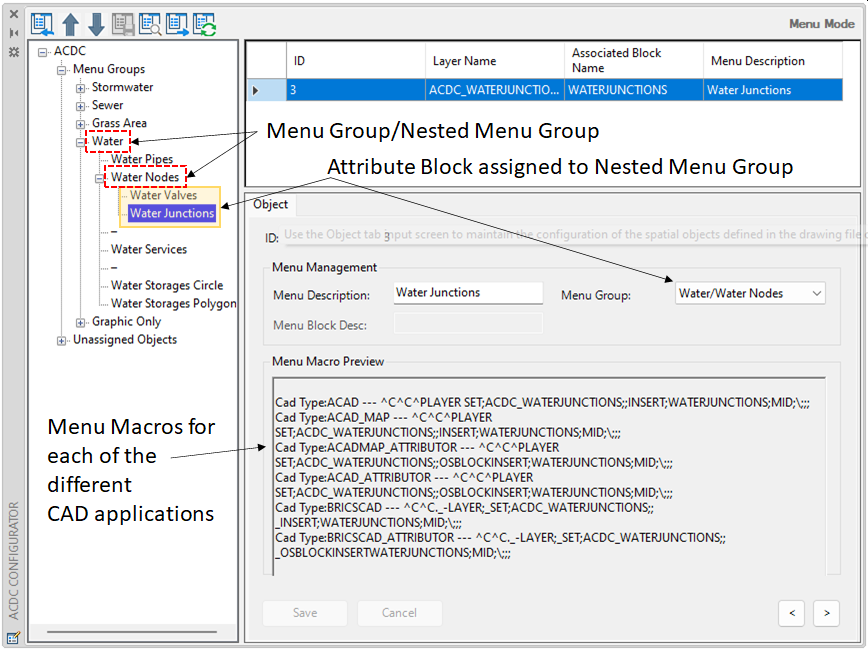
Fig: Menu Mode displaying Menu Groups and Nest Menu Groups with assigned Attribute Blocks
Once the Menu is generated as a .mnu and loaded in AutoCAD / BricsCAD using the MENULOAD command, the menu is compiled, and the Attribute Blocks are displayed as menu items so they can be placed in the drawing by simply selecting the required menu option.
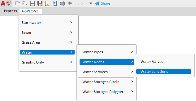
Fig: Resultant Menu layout when loaded in AutoCAD
Menu Buttons
Below is an explanation of the functionality of the buttons in Menu Mode.
 Edit ACDC Configuration - Switches the Configurator to Configuration Mode if in Menu Mode.
 Move menu item/group up - Moves selected Menu Group or Separator up the menu structure tree.
 Move menu item/group down - Moves selected Menu Group or Separator down the menu structure tree.
 Save menu layout - Saves the menu layout to the database. This button is only available once a change has been made.
 Preview menu layout - Displays a preview of the configured menu layout.
 Generate menu - Generates the menu as an .mnu file.
 Refresh data - Refreshes the Menu Mode with the data stored in the ACDC system tables. It also refreshes the left tree view pane with all the Menu Groups.
Menu Mode Tree Pane
The ACDC Tree Pane displays two branches, namely Menu Groups and Unassigned Objects.
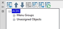
Fig: ACDC Tree Pane
The Menu Groups branch can be expanded to display the various menu groups configured in the menu structure.
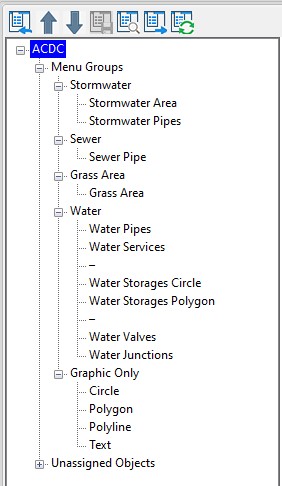
Fig: Expanded Menu Groups
The Unassigned Objects branch can be expanded to display Menu items which have not yet been assigned to a Menu Group.
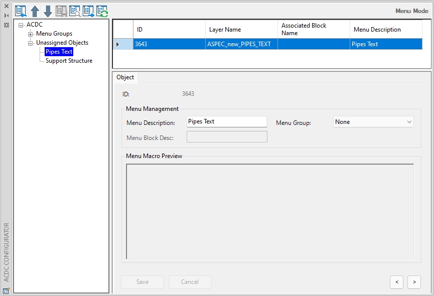
Fig: Expanded Unassigned Objects
Menu Mode Tree Pane Context Menu
The following context menu options are available when right clicking inside the Tree Pane:
- Refresh Data: Refreshes the Tree Pane with the data stored in the ACDC system tables.
- Sort Ascending: Sorts the Tree Pane in Ascending order.
- Sort Descending: Sorts the Tree Pane in Descending order..
- Expand All: Expands all branches in the Tree Pane.
- Collapse All: Collapses all branches in the Tree Pane.
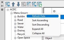
Fig: Menu Mode Right Click Context Menu
 after sorting.
Adding a New Menu Group
To add a new Menu Group, complete the steps below:
- Select the Menu Groups node in the left tree pane view.
- Right-click in the content pane and select the Add Record option.
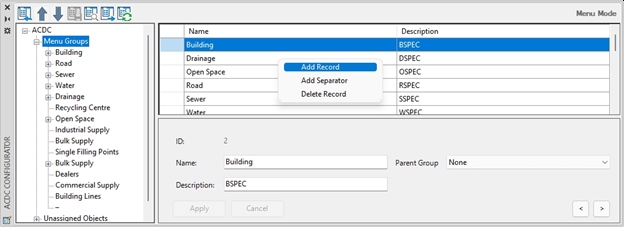
Fig: Adding a New Menu Group
- Enter a unique Menu Group Name and meaningful Description whilst leaving the Parent Group as the default value of None.
- Once complete, select the Apply button where the dialog box will automatically refresh and display the new Menu Group in the tree pane..
- Selecting the Cancel button will prompt the user to confirm they want to discard the changes.

Fig: Selecting the Cancel option when creating a new Menu Group
- You can change the order of the Menu Group records by using the Up
 or Down
  arrow buttons.
 - Select the Save Menu Layout button
 to save the menu configuration changes to the ACDC configuration database.
Adding a Nested Menu Group
To add a nested Menu Group to an existing Menu Group, complete the steps below:
- Select the Menu Groups node in the left tree pane view.
- Right-click in the content pane and select the Add Record option.
- Enter a unique Menu Name and meaningful Description and select the Parent Group to which you want the menu item to be assigned to from the drop-down list.
NOTE: The Parent Group drop-down list corresponds to the Parent Group menus listed in the Menu Groups node in the left tree pane view.
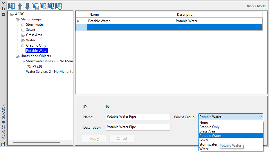
Fig: Adding a New Menu item and assigning to a Menu Parent Group - Once complete, select the Apply button where the dialog box will automatically refresh and display the nested Menu Group under the selected Parent Group in the tree pane.
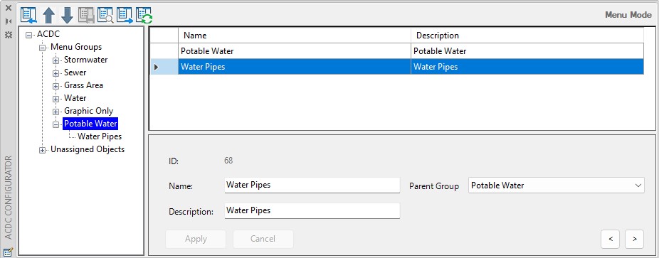
Fig: Result of adding new Menu item and assigning to a Menu Group
- You can preview the layout of the menu by selecting the Preview menu layout button
 and navigate through the menu groups and associated menu items.
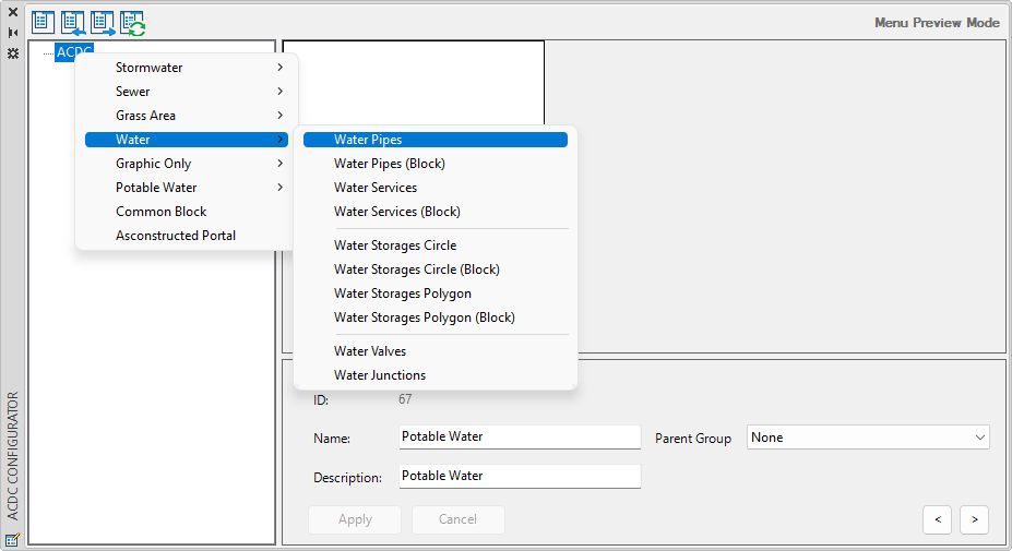
Fig: Preview menu layout
- Select the Edit ACDC menu layout configuration button
 to return to Menu Mode.
Delete a Menu Group
To delete a Menu Group, complete the steps below:
- Expand the Menu Groups node in the left tree pane view.
- Select the Menu Group to be deleted. The Menu Group record will be populated in the content pane.
- In the content pane, select the record to delete so that it is highlighted, and then right click and select the Delete Record option.
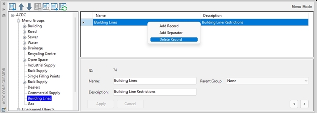
Fig: Delete a Menu Group
- The user is presented with the ACDC Configurator – Delete Menu Group confirmation message. Select Yes to confirm deletion or No to cancel and return to the content pane.
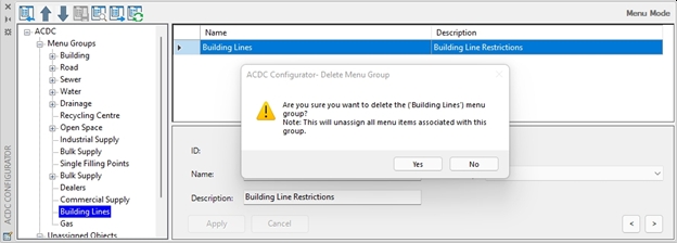
Fig: Delete Menu Group confirmation message
- Upon successful deletion, the Tree Menu is automatically refreshed, and the deleted Menu Group record is removed.
- Select the Save Menu Layout button
 to save the changes to the ACDC configuration database.
NOTE: When deleting a Menu Group the deletion process un-assigns all menu items associated with the Menu Group. These menu items can be viewed under the ‘Unassigned Objects’ node in the tree pane.
Add Menu Separator
To add a new separator between Menu Groups or nested Menu Groups, complete the steps below:
- Select the Menu Groups node in the left tree pane view.
- Right click in the content pane and select the Add Separator option
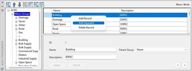
Fig: Add Separator from context menu
- This will add a new Separator node to the bottom of the list of Menu Groups.
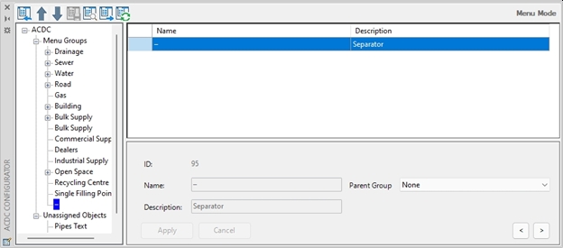
Fig: Add Separator record
- The Separator node can be moved up or down the menu structure using the Up
 or Down
  arrow buttons.
 - Select the Save Menu Layout button
 to save the changes to the ACDC configuration database.
 - The Separator will display as a separation line when selecting the Preview Menu
 option.
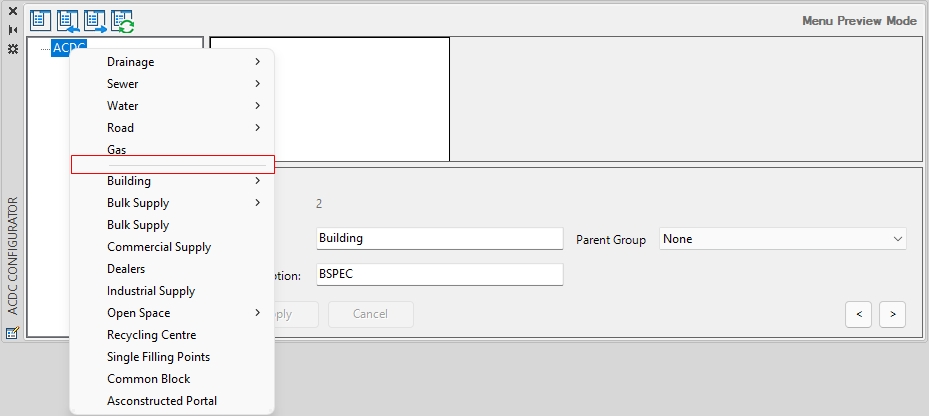
Fig: Separator in Preview Menu
Generate Menu
Selecting the Generate Menu icon  generates the menu layout and allows the user to save as a menu (.mnu) file. The user is prompted to add the following:
- Menu Type: The user must select one option from the drop-down list which consists of the following Menu Types:
- ACAD.
- ACAD_ATTRIBUTOR.
- ACAD_MAP.
- ACADMAP_ATTRIBUTOR
- BRICSCAD.
- BRICSCAD_ATTRIBUTOR.
- Group Name: Partial customization File name, for example ASPEC_V3.
- Menu Name: Menu Name which is displayed on the Menu bar when the menu is loaded within AutoCAD or BricsCAD, for example A-SpecV3.
The user is then prompted to Save the .mnu file by typing in a Menu File name and the location where the menu file can be loaded into AutoCAD, AutoCAD Map to BricsCAD.
Once the menu is loaded in AutoCAD or BricsCAD using MENULOAD command, the menu is compiled and appears in the Menu Bar at the top of the screen.

Fig: AutoCAD Menu bar displaying Partial Customized Menu A-SpecV3
The MENULOAD command generates the Customized User Interface menu files (.cuix for AutoCAD or .cui for BricsCAD) which can be opened and tweaked in AutoCAD or BricsCAD using the CUI command.
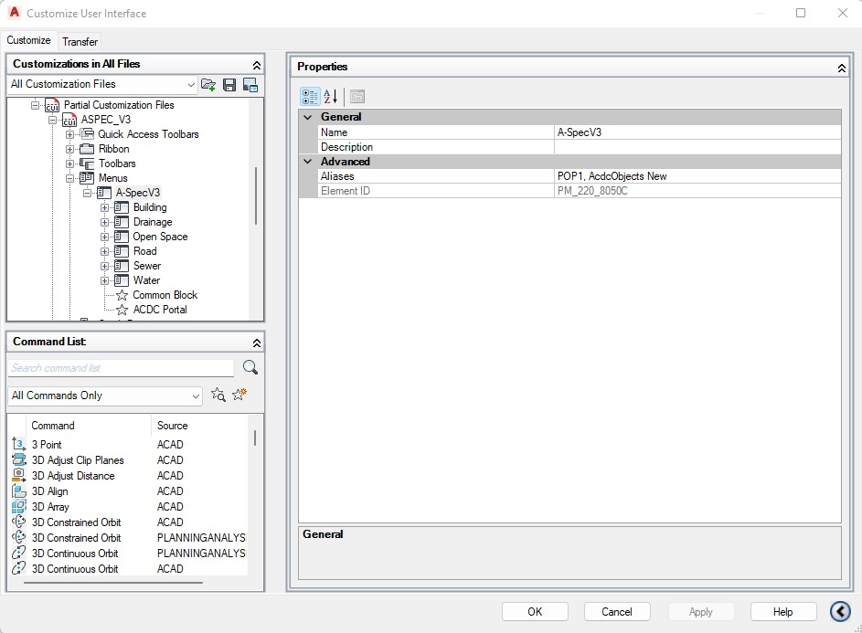
Fig: AutoCAD Customize User Interface (CUI) in AutoCAD
Using AutoCAD’s CUI command (Customize in BricsCAD) the Macros assigned to the various menu items can also be edited.
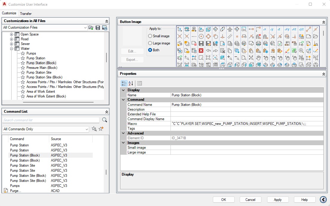
Fig: AutoCAD CUI to edit Macros.