Validation Process
The Validation process compares the data in the open drawing file with the stored configuration and validation rules in the database. These rules are constructed during the configuration process. Data in the drawing that violates the defined rules will be flagged as errors and must be addressed before the data can be converted. Once all errors are addressed, the Validator will construct all the required attribute information into the format defined in your configuration. The attribute information for each asset in the open drawing will be stored in object data tables created on each applicable object in the drawing.
If a drawing has already been validated, the system will display the following message on the command line: Drawing already validated - exiting routine. The routine automatically exits and does not delete the Object Data tables.
If the user clicks on cancel, while it is still processing objects then orphan records will also be removed from the WAE_ERRORS_OBJ database table.
If the drawing has not yet been validated then the system will proceed with validation and delete the object data tables. When this happens, drawings which has previously been validated may have changed geometry objects such as splitting of linear objects.
Compound Validations
Compound Validations allow users to configure additional attribute, spatial or a combination of attribute and spatial rule checks, based on comparisons, ranges, limits, multi value lists etc. These additional Compound Validations can be categorized into three main types:
- Compound Attribute Validations.
- Compound Spatial Validations.
- Compound Spatial/Attribute Validations.
The table WAE_ATTR_RULEMAP maps the various Compound Validations error types (WARNING or ERROR) for different rule type configurations. This table also sets the order in which the rules are applied. The rule parameters determine what criteria the rules must meet in order to pass or fail.
There are various Rule Types that can be configured as per the examples provided below:
- Compound Attribute Validations (Examples).
- FORMATSTR: Checks for a single character in a text string and if matches returns True, no match returns False.
- SUBSTR: Checks for a specific character, or string of characters in a sequence, applies the operator defined and returns a False if criteria is not met, and the Error is logged.
NOTE: See the list of permitted operators include: equal to (EQ), not equal to (NEQ), greater than (GT), less than (LT), greater than and equal to (GTE), and less than and equal to (LTE). - MVCHECK: Used for scenarios where if a pipe is captured with a certain material, then the permitted pipe diameter must match what is configured.
NOTE: Where the rule type is configured as MVCHECK, the list of configured multi value attributes are stored in the table WAE_ATT_MVRULECHECK. - COMPARECHECK: Used for scenarios where if, in the example of gravity mains, the upstream manhole invert level must be greater than the downstream invert level.
- MULTICHECK: Used for scenarios where if a Storm water manhole is captured exceeding a specific depth, there needs to be a certain number of rungs captured for access to the pipe.
- RANGEEX: Checks if a value falls within a specified minimum and maximum range of values. Exception values can also be specified.
- VALUECHECK: Checks if a number value is equal to (EQ), not equal to (NEQ), greater than (GT), less than (LT), greater than and equal to (GTE), and less than and equal to (LTE) a specified numeric value.
- Compound Spatial Validations (Examples):
- ISINSIDE: Checks to make sure there is a certain object falls within another object, for example: a Road Center-line must be captured within a Road Surface Area.
- LINKLIMIT: Checks if more than one pipe exits from a single node such as a manhole.
- NODELIMIT: Checks on a pipe with connecting valves that the minimum number of valves permitted is one and maximum is 2.
- Compound Spatial/Attribute Validations (Examples):
- RACHECK: Related Attribute checks for example: The diameter of a fitting must match the diameter of the pipe
- CHECKLINK: Checks where an attribute value assigned to one object matches another object’s attribute value based on a spatial link between the two objects such as object one being INSIDE, or CROSSING the second object.
- DISTCHECK: Checks the number of secondary objects WITHIN/MAX/MIN distance of the primary object. Used in scenarios to generate warning/error messages if a road center-line within a road polygon does not have matching road name.
NOTE: Currently, the compound validations are configured on the customer database by means of SQL scripts. It is recommended that you contact the Support Team at Open Spatial to assist with determining and configuring these validation rules.
Run the Validate ACDC Drawing Tool
To complete the validation process, follow the steps below.
- Open ACDC application by selecting the ACDC icon on the desktop.

- Open the AutoCAD drawing file to be validated by typing the AutoCAD command Open at the command line, and navigate to the required drawing.
- On the ACDC Toolbar press the Connect to Database button
 and connect to the required configured database which contain the ACDC system tables.
 - On the ACDC Toolbar press the Validate ACDC Drawing button
 .
. - When prompted to overwrite the validation report file, select the appropriate option (Y will overwrite all data in the report file, while N will add the new information to the end of the file). You can inspect this file for a list of all the validation errors.
- When prompted to select the objects based on Current or All configured layers, if the selection parameter is set to All then all configured layers present in the drawing will be turned on (thawed). If the selection is set to Current then layers which are not configured will be turned off/frozen.
- Select the objects you wish to validate against your stored configuration. You can do this by either manually selecting the objects in your drawing using the mouse, or you can simply type All to select all the objects within the drawing file. It is recommended that you always run the Validator on ALL objects in your drawing.
- Press the Enter key on your keyboard, or press the right-button on your mouse to begin the validation routine.
- The command line provides feedback for the number of entities being processed based on the number of objects selected.

Fig: Validation Process Progress on Command Line. - Upon completion, the results of the validation routine will be displayed on the command line. Select F2 button to display an expanded view of the Command Line to be able to view all the results.
Error Message Handling
If errors were detected during the Validation Process, the error messages are written to the log file, using similar syntax as illustrated below:
[Number of objects] [Entity Type(s)] on layer [Entity Layer] skipped. Entity Type not valid in configuration
An error message will also be printed on the command line and error circles will be placed in the open drawing file.
If any errors are picked up during the validation process then the Enhanced Attribute Editor dialog will be displayed. In this the error blocks will be displayed with the entity name (blockname) or object type and layer name. This will avoid any confusion the user may have as to which error pertains to which block or object type on which layer.
When validating a geometry type, if the drawn geometry type does not match the configured geometry types for line, point and polygon objects, the system will display an error in the validation results in the following syntax e.g. Incorrect Object Type (SPLINE). - [Layer: OSPEC_NEW_AREA_EXTENT].
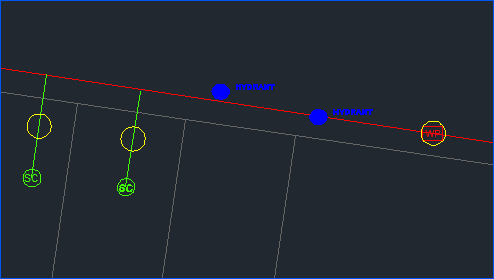
Fig: Objects with Attribute Errors Flagged with Yellow Circles.
As part of the Configurator Settings, the default color of the Error and Warning circles can be set for Attribute Errors/Warnings, Geometry Errors/Warnings, Break Errors/Warnings and Database Extents Errors/Warnings.
- gAttributeErrorColour: Default color set to Yellow.
- gAttributeWarningColour: Default color set to Yellow.
- gCannotBreakErrorColour: Default color set to Cyan.
- gCannotBreakWarningColour: Default color set to Cyan.
- gExtentsErrorColour: Default color set to Magenta.
- gExtentsWarningColour: Default color set to Magenta.
- gGeometryErrorColour: Default color set to Red.
- gGeometryWarningColour: Default color set to Red.
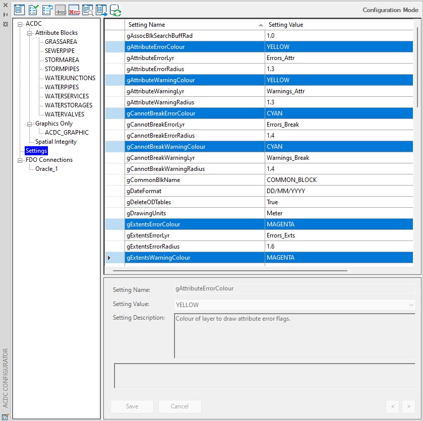
Fig: Configurator Error and Warning Circle default settings.
Below is a screen shot of a flagged geometry error (red circle). In this case the error is that the closed polyline object contains two attributed blocks.
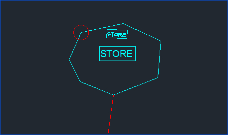
Fig: Red Circle Flagged Geometry Error.
A report file (.log file) is also created by the ‘Validate ACDC Drawing’ tool. The report file is given the name specified by the gReportFile setting and is placed in the directory specified by the gReportFileLocation setting. By default, the report file name and location are set to be the same as the currently open drawing file. The report file contains a log of all the errors found during validation. For each error the report file will contain its coordinates, the created error block name, and the associated error message.
- To view the details of an error, simply select an error circle (Red for geometry errors and yellow for attribute errors) and view the error circle properties. The error information is contained in the ‘Block’ section of the properties dialog. As per the example below, one object or block may have more than one error listed in the properties pane.

Fig: Error Properties - Address each error and fix accordingly.
- Once you have addressed each flagged error, run the Validator once again on all of the data in the drawing. If all errors have been fixed successfully, you should see zero counts against the different error types in the command line and should check the number of objects selected vs the number of objects passed.
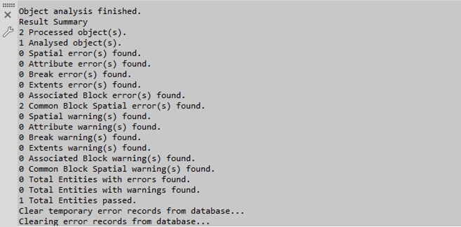
Fig: Successful Validation RunThe above command line feedback indicates a successful validation run. On a successful validation run, the data within your initial selection passes all validation checks. As such, these objects are recorded as validated and will not be re-inspected by the Validator on subsequent validation runs.
Errors which are picked up during validation are stored within WAE_ERRORS_OBJ database table. When an error is flagged, it will be displayed in the below syntax, where the xxx variables indicate the Layer Name and the yyy variables the Block Name respectively. This will be displayed in both the WAE_ERRORS_OBJ database table and the resultant Log file.
Error Message - [Layer: xxx - Block: yyy]
for example:
WAE_ERR_190,Error: Invalid substring (RD) compare for tag (MATERIAL) - [Layer: ACDC_STORMPIPES - Block: STORMPIPES]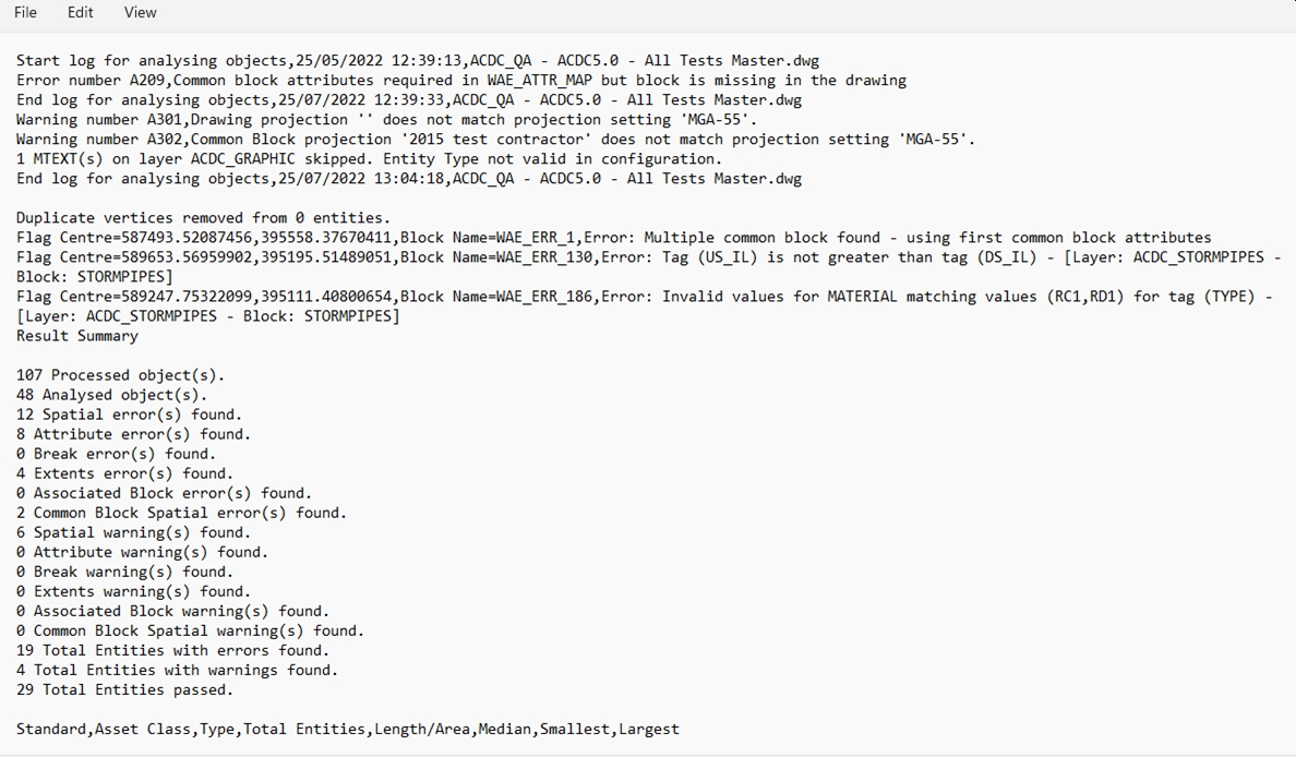
Fig: Errors written to Log fileThe log file also contains a detailed report on all Asset classes that are in the project and are listed according to the Layer and Geometry type with the following extended information:
- Class.
- Type.
- Total Entities.
- Length / Area.
- Median.
- Smallest.
- Largest.

Fig: Detailed Asset Classes reportOnce a validation has been run, the table WAE_ERRORS_OBJ is automatically truncated to prevent historic errors from being flagged. Validated objects will have their final attribute information recorded in object data tables. To view this information, select a validated object in your drawing and view its properties. You will see that an OD section has been added to the feature that contains all applicable attribute information:

Fig: Validated Object AttributesThis information is what will be transferred across to your destination tables in the conversion process.
In the properties dialog of a validated object you will also see a section titled OD: ACDC_VALIDATED. This indicates that the object has been validated.

Fig: Validation ConfirmationIn a successful validation run, snapping and breaking rules will be carried out on all the selected objects.
- OSX_AP_SETTINGS: Stores the settings information used during the Validation and Conversion processes.
- WAE_OBJECT: Defines the objects to be Validated/Converted, their geometry types, associated blocks, and destination layers.
- WAE_ATTR_MAP: Stores the definition of attributes to be stored for each defined object type.
- WAE_PIPE_BREAK: Lists the details of defined snapping rules.
- WAE_SC_LINK: Defines the layers that contain objects to which service connection can connect.

Fig: Configurations loaded at the start of Object ValidationThe user is then prompted to overwrite the report log file or not. By default No will append the entries from the validation process to the existing log file. If the user selects Yes to overwrite, the log file is re-created during the validation process.

Fig: Overwrite log fileWhen the user is running a validation on the selected objects, the system will display a prompt: Select objects based on current or all configured layers? [Current All] :
- The Current option will turn off all layers and only displays those layers that have been configured as part of the Configurator.
- The All is selected then the routine will not change any layers (turning them on or off) when the user is prompted to select objects to validate.

Fig: Later selection for Validation
Table 7- Validate ACDC Drawing Checks
Below is a list of the checks performed by the Validate ACDC Drawing tool.
| No. | Description | Expected Result |
| 1 | Error: [count] attribute blocks found | Geometry error flagged |
| 2 | Error: [count] attribute blocks found at end of this SC | Geometry error flagged |
| 3 | Error: [count] attribute blocks found at start of this SC | Geometry error flagged |
| 4 | Error: Associated block is contained within more than one configured object | Geometry error flagged |
| 5 | Error: Associated block is not contained within configured object | Geometry error flagged |
| 6 | Error: Associated Block on incorrect layer- [Layer Name - Block Name] | Geometry error flagged |
| 7 | Error: Cannot break pipe as new segments too short | Break error flagged |
| 8 | Error: Cannot break pipe at this location | Break error flagged |
| 9 | Error: Cannot break. Ambiguous destination points | Break error flagged |
| 10 | Error: Cannot retrieve function for [TagName] | Attribute error flagged |
| 11 | Error: Cannot retrieve procedure for [TagName] | Attribute error flagged |
| 12 | Error: Cannot retrieve sequence for [TagName]. Check ACDC configuration. | Attribute error flagged |
| 13 | Error: Cannot retrieve tag [TagName] | Attribute error flagged |
| 14 | Error: Cannot snap block. Ambiguous destination points | Break error flagged |
| 15 | Error: Configuration indicates LWPolylines on this layer should be closed. | Geometry error flagged |
| 16 | Error: Date value is in an invalid format for tag [TagName] - [Layer Name - Block Name] | Attribute error flagged |
| 17 | Error: Entity area [area] is less than minimum tolerance [tolerance] allowed | Geometry error flagged |
| 18 | Error: Entity found outside of configured ACDC extents. | Geographic extents exceeded |
| 19 | Error: Entity length [Length] is less than minimum tolerance [Tolerance] allowed | Geometry error flagged |
| 20 | Error: Incorrect Object Type [ObjectType] on layer [Layer Name] | Geometry error flagged |
| 21 | Error: Invalid LCODE for tag [TagName] - [Layer Name - Block Name] | Attribute error flagged |
| 22 | Error: Invalid numerical value for tag [TagName] - [Layer Name - Block Name] | Attribute error flagged |
| 23 | Error: Invalid string value for tag [TagName] - [Layer Name- Block Name] | Attribute error flagged |
| 24 | Error: Invalid values for [Tag] matching values [Tag Values] for tag [TagName] - [Layer Name- Block Name] | Attribute error flagged |
| 25 | Error: Isolated configured block found | Geometry error flagged |
| 26 | Error: Missing mandatory value for tag [TagName] - [Layer Name- Block Name] | Attribute error flagged |
| 27 | Error: More than one object found with associated block [Layer Name] | Geometry error flagged |
| 28 | Error: Multiple common block found - using first common block attributes | Geometry error flagged |
| 29 | Error: No attribute block found - [Layer Name] | Geometry error flagged |
| 30 | Error: No attribute block found - [Layer Name] at end of this SC | Geometry error flagged |
| 31 | Error: No attribute block found - [Layer Name] at start of this SC | Geometry error flagged |
| 32 | Error: No main pipe found at end of this SC | Geometry error flagged |
| 33 | Error: No main pipe found at start of this SC | Geometry error flagged |
| 34 | Error: No main pipe found to connect to this SC | Geometry error flagged |
| 35 | Error: No objects found on correct layer | Geometry error flagged |
| 36 | Error: No valid object layer/type combination found | Geometry error flagged |
| 37 | Error: Numerical value too large for tag [TagName] - [Layer Name - Block Name] | Attribute error flagged |
| 38 | Error: Numerical value too small for tag [TagName] - [Layer Name - Block Name] | Attribute error flagged |
| 39 | Error: Point within Snap Tolerance | Geometry error flagged |
| 40 | Error: String too long for tag [TagName] - [Layer Name - Block Name] | Attribute error flagged |
| 41 | Error: Value is not an integer for tag [TagName] - [Layer Name - Block Name] | Attribute error flagged |
| 42 | Error: Width of number too large for tag | Attribute error flagged |
| 43 | Warning: Common block could not be found in the drawing. | Warning |
| 44 | Warning: Drawing Projection does not match projection setting | Warning |
| 45 | Warning: Common Block Projection does not match projection setting | Warning |
Notes on Object Data
- Validated objects (as indicated by the ACDC_VALIDATED object data table) are not reviewed by the Validate ACDC Drawing tool on subsequent validation runs. If you need to re-validate an object, you must remove its existing object data. To remove existing object data, use the Delete Object Data Tables button . When you press this button, you are presented with two options:
- Tables: This option will remove all object data tables from all objects in the drawing. You must use this option if you have made some changes to your configuration.
- Selection: This option will remove object data tables from only the selected objects.
With object data removed, the Validate ACDC Drawing tool will view the selected objects as un-validated and will subject them to a complete validation check.
- Tables: This option will remove all object data tables from all objects in the drawing. You must use this option if you have made some changes to your configuration.
- Care must be taken when using the Delete Object Data Tables tool. If you remove object data from an object that has been split (broken) by the Validate ACDC Drawing tool, these objects will be viewed as two completely separate objects by the Validator on subsequent validation runs. The Validator will now expect both of these objects to have their own associated blocks, which will not be the case because they were a single object in the original drawing. This means that objects that have been split by the Validator and then have their object data removed will not pass subsequent validation runs. Therefore, you should not ever remove object data from objects that have been split by the Validate ACDC Drawing tool.
- The user must ensure that no forward slash character ("/"), is used in the object data field names, suggest the user uses the underscore instead ("_").
- ACDC Validator now also handles MPOLYGON object class type, where object data can be copied over to the MPOLYGON.
- The Validator now has improved performance where the selection is improved on common block entities when attaching attributes, and now only selects a block once and not every time attributes are attached to an object.
- Ability to handle MTEXT features are catered for, to prevent the user from exploding these features and losing the core benefits of formatting etc. This function now generates a line from the base-point to position 1 of the block. It also inserts a small circle at the base-point with an arrow-head on the other side of the line. This arrow-head has the capacity to resize itself based on the percentage of the line length to handle short lines more effectively. Fundamentally this functionality also allows for the incorporation into both straight lines and multi-segment lines.
- Additional related attribute validations are done on sewer and drainage pipe directions based on Start and End Invert Levels to ensure the pipe flow direction is correct in terms of the linear direction of the line object.