Overview
The enlighten Administration view provides you with a powerful tool for performing enlighten administration tasks through an easy-to-use web interface.
User’s with administrative privileges have access to a special section of the enlighten site that is not visible to normal enlighten users. This is identified as the Administration View and provides users with a powerful tool for performing enlighten administrative tasks through an easy-to-use web interface.
To access enlighten Administration View, first log on to enlighten using the administrator username and password. The enlighten Web Map will load (please refer to the enlighten User’s Guide for more information about enlighten map functionalities).
If you have been granted one or more administrative privileges then you will be able to access this function by first opening the enlighten Task Pane by selecting the Task Pane icon ![]() on the Main Toolbar, and then selecting the Admin View icon
on the Main Toolbar, and then selecting the Admin View icon ![]() .
.
The enlighten Administration View land page shows the options available to a user with all administrative privileges. A user with restricted administrative privileges would have fewer menu items available.

Fig: Admin View Landing Page
The Administration View is divided into into the following administration groups:
- Site Administration: Customize the enlighten Home page. Update enlighten with the latest documentation and FAQ's.
- Map Administration: Administer the customisable enlighten Mapping functions.
- User Administration: Add, edit and delete users from the system. Manage Layer and Function access.
- Log Administration: View and delete the User and Administrator Logs created by the system.
The remainder of this document will outline the administrative functions available in each of the groups mentioned above. This will also instruct the site administrator on how to configure and customize these functions.
Site Administration
The Site Administration section allows the administrator to customize the enlighten website and for the download of the latest enlighten documents provided by Open Spatial.
The Site Administration functionalities are arranged in the following groups:
- Disclaimer: Customize the enlighten disclaimer page.
- Customize Homepage: Customize the enlighten homepage with your own logo, welcome message, and contact details.
- Broadcast News: Broadcast a news message to all enlighten users. This will appear in the right-hand side pane of the Map View.
- Documentation: View admin documents, download the latest documentation from the Open Spatial Servers or add your own.
- Security Settings: Customize the password and general site security settings.
- Configure Settings: Mange EN_SETTINGS table.
- Configure Network Trace Settings: Configure Network Trace Settings.
- Plot Engine Status: Show Plot Engine Status.
- Active Users: Show Active Users with Actions History.
 Disclaimer
The Disclaimer tab allows you to customize and enable the license agreements page. The title and content of the license agreement section can be added in or edited. HTML tags will be rendered as formatted in the contents section. Once information is entered in the fields a review option becomes available.
Click the review button to see what the formatted agreement will look like and either accept or decline. When you are ready to submit the license agreement, select the Save button.
The License Agreement can be enabled or disabled by clicking on the checkbox next to Enable License Agreement. If the Disclaimer is Enabled users will be presented with the Disclaimer message to Accept before they are taken to the enlighten map. If the user Declines the Disclaimer, they are immediately returned to the enlighten Home page.
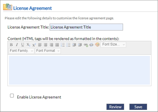
Fig: License Agreement
Customize Homepage
The Customize Homepage tools allow you to customize features of the enlighten homepage.
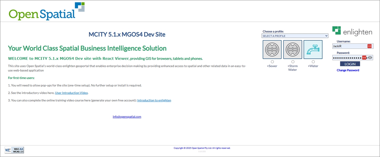
Fig: The enlighten Homepage
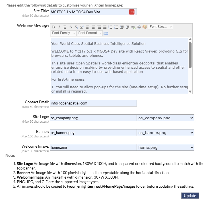
Fig: Customize Homepage
The enlighten homepage is composed of the following customisable sections:
- Site Title: This will be any suitable title chosen by your organization to be displayed at the logon screen.
- Welcome message: This is the message that will appear on the enlighten homepage. Enter a welcome message that will be relevant to the organization’s users.
- Contact Email: This is the email address of the enlighten administrator. This person will receive support requests from other enlighten users sent through the Support page. Details on configuring the email are included in the Enlighten 5 Installer document.
- Site Logo: This is the image that will appear in the upper left-hand corner of the homepage and introductory pages. If using the company logo, please ensure it is resized to 180W x 100H pixels and has a transparent or colored background to match with the top banner.
- Banner: This will replace the blue background behind the logon prompt. The image should be 100 pixels high and should be repeatable along the horizontal direction. This should be configured to match screen size and resolution.
- Welcome Image: This will replace the default Open Spatial image on the welcome page. The image should be 307W x 500H pixels.
 Broadcast News and Quick Links
In this section, the administrator can enter a News message that will be visible to all enlighten users. The message will appear in the right-hand side pane of the Map View.
The Broadcast News is composed of the following customisable sections:
- Broadcast News.
- Quick links.
Broadcast News allows the administrator to enter a message that will be displayed to all users on the Enlighten Task Pane when logging into the enlighten application.
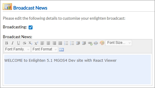
Fig: Editing Broadcast News
Quick Links is where the administrator can add or edit hyperlinks. The hyperlinks are added as HTML.
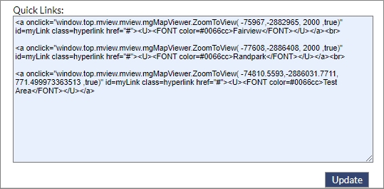
Fig: Edit Quick Links
Both the Latest News message and the Quick Links are displayed on the Enlighten Task Pane in the map view when the user opens the Enlighten Task Pane  icon.
icon.
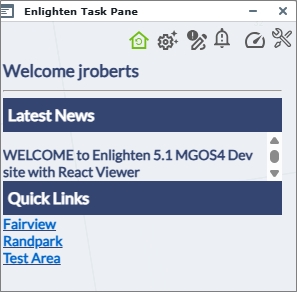
Fig: Enlighten Task Pane
For more details on quick links please contact support@openspatial.com.
Documentation
This section contains a link to all the latest enlighten administrator’s documentation. Once selected the documents are loaded in a separate browser window for viewing as either an HTML online document or as a PDF file.
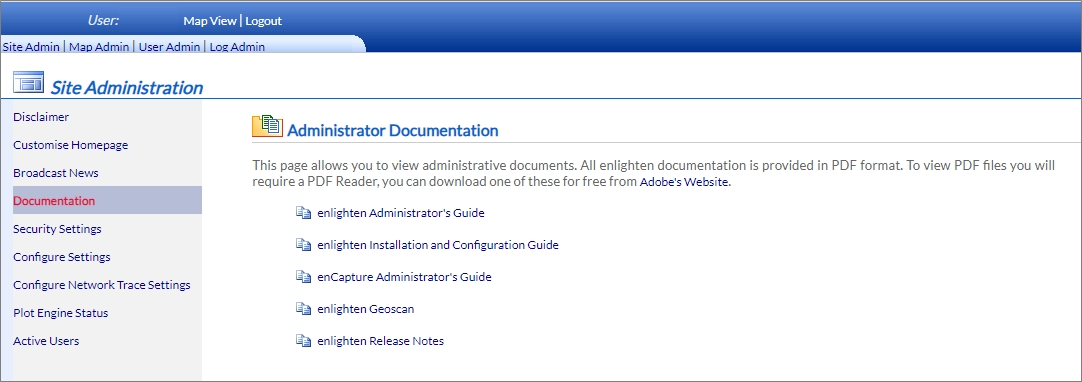
Fig: Administrator Documentation
 Security Settings
To configure the security of the enlighten website the following steps can be followed:
General Settings
To setup Security Settings the following steps can be followed:
- Navigate to Admin View > Site Administration > Security Settings.
- Customization of the General Settings can be setup in enlighten, and are outlined below:
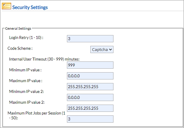
Fig: General Settings- Login Retry: This setting manages the total number of retries allowed before the secure login code is displayed. The Login Retry value should be between 1 and 10 if this is exceeded an error “invalid code” is returned. The Captcha screen is then displayed for the user to enter credentials. The Login Retry value is set to 3, by default within enlighten.
- Code Scheme (Login Code Delivery Scheme): The login code delivery scheme refers to the mechanism used to deliver a secondary security code. If a user fails to perform a successful log-in within the allotted number of tries (as determined by the Login Retry setting) the system will require a secondary security code in addition to a valid username and password. The secondary security code is delivered using one of many different delivery methodology options, including:
- CAPTCHA: The CAPTCHA code delivery scheme creates a noisy distorted image with the security code embedded in the image. The value from the CAPTCHA image needs to be entered together with the username and password. The system uses a CAPTCHA method by default. Other methods require special configuration and/or hardware integration. For more information on other methods, please contact support@openspatial.com.

Fig: Security Code Captcha - CAPTCHA will be installed as the default code scheme, but different schemes are possible, for example:
- SMS
- CAPTCHA: The CAPTCHA code delivery scheme creates a noisy distorted image with the security code embedded in the image. The value from the CAPTCHA image needs to be entered together with the username and password. The system uses a CAPTCHA method by default. Other methods require special configuration and/or hardware integration. For more information on other methods, please contact support@openspatial.com.
- Internal User Timeout: The time (in minutes) the system can remain idle before the session will expire and the user will be forced to log in again. Acceptable values will be between 30 and 999 minutes.
Note: Refer to the Enlighten Installer Guide, under the Configuring Session Timeout section for more information. - IP Ranges: The IP ranges specified here are used to determine if a user is an internal or external user (Note: If only one IP range is available, this needs to be duplicated for the second range. Null values are not accepted). Users with an IP address within the configured IP ranges for enlighten are flagged as internal users. All enlighten functionality is available to internal users. Users with an IP address outside of the configured IP ranges are flagged as external users. External users will only have access to the following security hardened features of enlighten:
- Searches.
- Plot Applications.
- Map Navigation tools.
- Show Info forms (but external users will not be able to edit or filter any data).
- Spatial Summary.
- Plot Engine Jobs per Session: The maximum number of plot jobs permitted per session. This variable allows the administrator to configure the number of jobs that can be sent to the plot engine queue per session and between 1 and 50 in a single session. Limiting this factor can protect the plot engine from viral attack.
Password Settings
The Password Settings section of the Security Settings administration area allows the administrator to customize the user passwords settings for enlighten. It is important for administrators to develop an organizational User Management Policy.
This policy should outline elements of the user management including:
- Password complexity:
- Length of the password.
- Sequencing contained in the password.
- Alpha and numerical mix contained in the password.
- Upper Case and Lower-Case character mix contained in the password.
- Special Characters contained in the password.
- Password expiry and warning periods.
Administrators need to define this policy before going live with the system as implementing new password policies will impact all users.
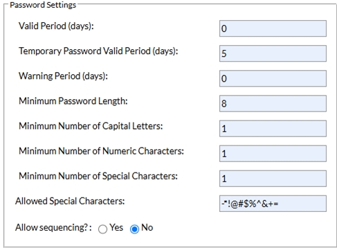
Fig: Password Settings.
- Valid Period (days): This setting sets the period, in days, for which a password will be valid. If the Valid Period is set to 0, passwords will not expire.
- Note: In this case, the Warning Period should also be set to 0. Any other value will automatically expire the user passwords after that period has expired. The period that a password is valid for, is set as a number of days (integer). This means that the expiry date is set to the date the user sets the password plus the number of days configured.
- If a user’s password reaches the end of its validity period, he/she will be allowed to log on as usual but will then be forced to reset the password before gaining normal access to the system.
- Temporary Password Valid Period (days): This setting sets the period, in days, for which a temporary password will be valid. A temporary password is that which is set by the enlighten administrator when creating or resetting a user’s password.
- Temporary passwords will grant access to the system but will force the user to set a permanent password. If the Valid Period is set to 0, the temporary passwords will not expire. Any other value automatically expires the temporary passwords after the period has expired. The period that a password is valid for, is set as a number of days (integer).
- This means that the expiry date is set to the date the administrator creates the user or resets the password, plus the number of days configured with this setting. If the temporary password reaches the end of its validity period, the user will not be allowed to change the password to a permanent password and will have to contact the system administrator to have it reset again.
- Warning Period (days): A password expiry warning period can also be set. If this is set to 0, no warning will be given. If the Warning Period is set to an integer larger than 0, the user will receive a Password is about to expire warning prior to actual expiry.
- Minimum Password Length: The minimum password length is the minimum number of characters for any valid password. This refers to the total length of the password, irrespective of the character mix in the password.
- Minimum Number of Capital Letters: This setting will force users to have a mixture of upper case and lower-case letters when choosing a password. If a number larger than 0 is set, then the system will check for the desired number of uppercase letters and always at least one lower case letter. Setting the value to 0 will disable the function that enforces mixed case; however, the password will still be case sensitive.
- Minimum Number of Numeric Characters: This setting will force users to have a mixture of alpha and numerical letters when choosing a password. If a number larger than 0 is set, then the system will check for the desired number of numerals and always at least one alphanumerical character. Setting the value to 0 will disable the function that enforces numerical characters, however, users can still use the numerical characters as part of their password.
- Minimum Number of Special Characters: This setting will force users to have a minimum number of special characters when choosing a password. If a number larger than 0 is set, then the system will check for the presence of special characters. See Allowed Special Characters below for more information on special characters. Setting the value to 0 will disable the function that enforces usage of special characters however users can still use special characters as part of their password.
- Allowed Special Characters: This field allow administrators to set which special characters the system will check for if Minimum Number of Special Characters above is set to some value larger than 0. The default list includes the following: - * ! @ & # $ % ^ + = .
- Sequencing (123..., ABC...): This setting will prevent users from setting passwords that are made up of sequences of two characters or more. The system will check for any three characters that form a sequence. Sequences can be either numerical, alphabetical or can be normal reversed.
Advanced Authentication Settings
- Single Sign-On: When the Enable Single Sign-On box is ticked, the user will be able to log in without entering any information. This is provided the user is assigned permissions by an administrator in the Assign Layers to Users function.
- LDAP: When the Enable LDAP box is ticked, a checkbox will be visible when the user logs on. If the user ticks this checkbox, the user can enter their windows username and password. To set this functionality, tick the Enable LDAP checkbox.
Note: The text LDAP at the beginning of the LDAP path name that you use must be in uppercase letters. If this is not in uppercase letters, then LDAP will not work. - LDAP://CN=User1,OU=Office1,OU=Users,DC=contoso,DC=com.
A breakdown of the abbreviations is outlined below:
- CN: Common Name.
- OU: Organization Unit.
- DC: Domain Component.
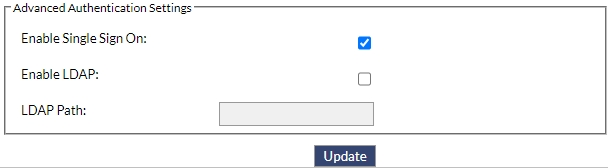
Fig: LDAP Settings..
The windows username will need to be added see Manage Users & Permissions, and any password can be used in this section as the user will use their windows password to log in.
Layers, functions, and permissions must also be assigned to users. See User Administration for more information.
If LDAP is configured, users will see a checkbox on the login screen that will need to be ticked to use LDAP login credentials.
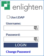
Fig: Use LDAP checkbox.
Improvements have been made to enhance security within Enlighten and have been hard-coded to ensure safety throughout the navigation of pages and some functionalities. Some of which features include and are not exclusive to:
- Verification checks to ensure searches does not accept SQL injection of reserved words.
- CSV export enhancements.
- Disabled access to Admin View function redirects the user to the error page.
- Ensuring pages load without being redirected to error pages.
- Verifications on csrf token validations within Forms and Searches.
Hardening is applied to both internal and external users to ensure safety mechanisms are in place. When Hardening is applied Externally then the users logging in externally will only have access to limited functionalities within Enlighten. Internal hardening ensures that users who don’t have access to certain pages by their administrator will not be able to navigate to that particular place. In summary, the essence of hardening avoids unauthorized users from navigating to pages, to which they don’t have access to. External hardening goes a step further by only allowing users access to Searches, enPlot, Navigation Tools (Zoom: Window, Previous, Next, Extent, Initial Centre and Scale), Pan, Select, Clear Selection, Reload Map, Show Info forms and Spatial Summary.
 Configure Settings
The Configure Settings processes within enlighten can be customized and features can be enabled via database settings. The features available for customization are shown below:
- Core
- Date Format
- enPlot
- Focus Integration
- Integration
- Map
- Property System Matching
- Network Trace
- Searches
- Show Info
- Shut Off Reports
- Site Security
When any of the settings listed below are updated, then the relevant application pool will need to be restarted for the changes to take effect.
| SETTINGS | |
| LOGIN_RETRY | PWD_NUMERIC |
| CODE_SCHEME | PWD_SPECIAL |
| INT_USER_TIMEOUT | PWD_SPECIAL_CHARS |
| HOME_OS_IMAGE | PWD_EXPIRY |
| MAX_PE_JOBS | TMP_PWD_EXPIRY |
| MOBILE_UNIT | PWD_EXP_WARNING |
| MOB_USER | MAX_IP |
| HOMEPAGE_BANNER | MAX_IP2 |
| PWD_LENGTH | MIN_IP |
| PWD_CAPITAL | MIN_IP2 |
Table: Settings requiring App Pool restart
Core Settings
Below is a list of the Core Settings which can be updated via the Site Administrator functionality in Enlighten.
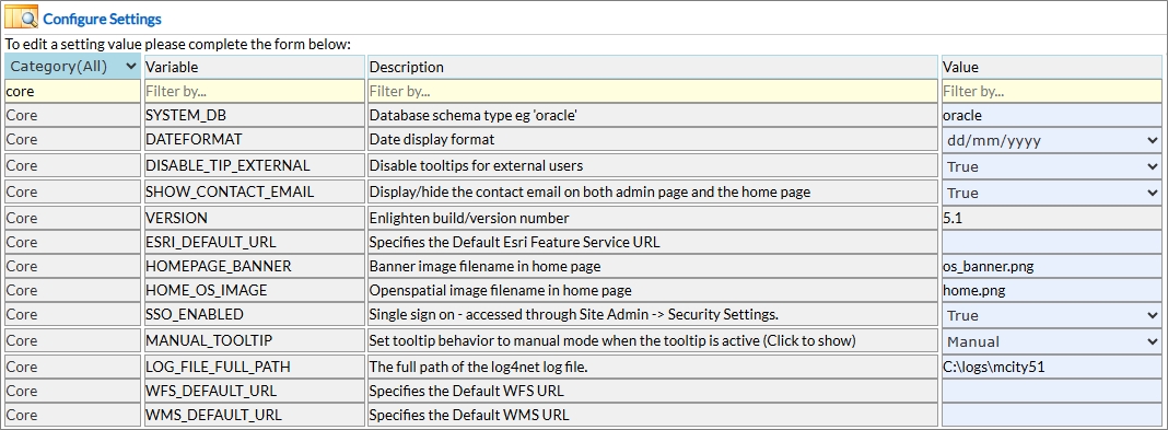
Fig: List of Core Settings
System Database
This setting sets the Systems database type. The default image is 'oracle'
To configure the settings the following steps can be followed:
- Navigate to Admin View > Site Administration > Configure Settings.
- Set Value to 'SQL' where Variable is 'SYSTEM_DB' to change the system database type set the Value to e.g. 'SQL'.
- To update the changes, click the Update button.
Display Date Format
This setting changes the System date format. The default format is 'dd/mm/yyyy' e.g. '13/01/2021'.
To configure the settings the following steps can be followed:
- Navigate to Admin View > Site Administration > Configure Settings.
- Set Value to 'dd/mm/yyyy' where Variable is 'DATEFORMAT' to change the System date format set the Value to e.g. '13/01/2021'.
- To update the changes, click the Update button.
Disable Tool-tips for External Users
This setting disables or enables the display of tool-tips for external users. The default setting is True where all configured external users do not have access to any of the tool-tip functions as listed below:
- Show/Hide Tool-tips icon on Enlighten Toolbar access is removed.
- OPTIONS on right-click Context Menu is removed.
- Manual Feature Tooltips on Manage User Options pane is removed.
To configure the settings the following steps can be followed:
- Navigate to Admin View > Site Administration > Configure Settings.
- Set Value to 'TRUE' where Variable is 'DISABLE_TIP_EXTERNAL' to disable tool-tips for external users.
- To update the changes, click the Update button.
Contact email
This setting enables or disables contact email on the Home Page and Admin Page. The default setting is enabled (YES) display contact email.
To configure the settings the following steps can be followed:
- Navigate to Admin View > Site Administration > Configure Settings.
- Set Value to 'FALSE' where Variable is 'SHOW_CONTACT_EMAIL' to disable the contact email set the Value to e.g. 'FALSE'.
- To update the changes, click the Update button.
enlighten Build/Version Number
This setting advises the enlighten administrator of the current enlighten build/version installed. Whenever enlighten is upgraded or a hot-fix applied, this setting is automatically updated via the upgrade/hot-fix SQL scripts to reflect the current version number.
This setting should NOT be manually updated since it is updated via the SQL scripts whenever enlighten is upgraded or a hot-fix is applied.
- Navigate to Admin View > Site Administration > Configure Settings.
- Check the Value where Variable is 'VERSION' to see the current version installed e.g. '5.1' or '5.0.6'.
ESRI Default URL
This setting is used to store the default URL for the ESRI Feature Service to allow users to add an ESRI Feature Layer to their maps via the Add/Manage External Layers option on the Main Toolbar. All ESRI Feature Services require a paid subscription or license, so please contact ESRI for your organization's plan details.
To configure the settings the following steps can be followed:
- Navigate to Admin View > Site Administration > Configure Settings.
- Set the Value to the required ESRI Feature Service URL where Variable is 'ESRI_DEFAULT_URL' for example:
'https://[server.name]/[folder.name]/ArcGIS/rest/services?f=pjson'. - To update the changes, click the Update button.
Home Page Banner image
This setting changes the Home Page banner image. The default image is 'os_banner_grey.png'.
To configure the settings the following steps can be followed:
- Navigate to Admin View > Site Administration > Configure Settings.
- Set Value to '[YourBanner.png]' where Variable is 'HOMEPAGE_BANNER' to change the image set the Value to e.g. '[YourBanner.png]'.
- To update the changes, click the Update button.
Home Page image
This setting changes the Enlighten Home Page image. The default image is 'home.png'
To configure the settings the following steps can be followed:
- Navigate to Admin View > Site Administration > Configure Settings.
- Set Value to '[YourCompany.png]' where Variable is 'HOME_OS_IMAGE' to change the image set the Value to e.g. '[YourCompany.png]'.
- To update the changes, click the Update button.
Single Sign On
This setting enables or disables Single Sign On for users. The default setting is disabled (NO) single sign on is needed.
To configure the settings the following steps can be followed:
- Navigate to Admin View > Site Administration > Configure Settings.
- Set Value to 'TRUE' where Variable is 'SSO_ENABLED' to enable single sign for users.
- To update the changes, click the Update button.
Set Tool-tip display behavior
This setting controls the way tool-tips are displayed using either the mouse-over on map object method, or the manual selection of the map object method. There are two options to apply to the configuration, namely:
- Automatic: applies the mouse-over option where the user simply moves and hold the mouse pointer over the required map object to display the tool-tip.
- Manual: applies the manual selection of the map object to display the tool-tip.
To configure the settings the following steps can be followed:
- Navigate to Admin View > Site Administration > Configure Settings.
- Set Value to 'Automatic' where Variable is 'MANUAL_TOOLTIP' to set the mouse-over tool-tip display option.
- To update the changes, click the Update button.
Log File Full Path
This setting sets the path for the log4net, a logging framework for .NET applications. Its main purpose is to help developers record information awhich can be used for trouble shooting and debugging.
To configure the settings the following steps can be followed:
- Navigate to Admin View > Site Administration > Configure Settings.
- Set Value to 'C:\logs' where Variable is 'LOG_FILE_FULL_PATH' to set the path for the log file.
- To update the changes, click the Update button.
WFS Default URL
This setting is used to store the default URL for the Web Feature Service (WFS) to allow users to add external Feature Layers to their maps via the Add/Manage External Layers option on the Main toolbar. The OGC Web Feature Service (WFS) is a standard protocol for serving Geospatial data as vector features with geometry and attributes which clients can use in Geospatial analysis.
To configure the settings the following steps can be followed:
- Navigate to Admin View > Site Administration > Configure Settings.
- Set the Value to the required Web Feature Service URL where Variable is 'WFS_DEFAULT_URL' for example: 'https://opendata.maps.vic.gov.au/geoserver/wfs?request=GetCapabilities&service=WFS'.
- To update the changes, click the Update button.
WMS Default URL
This setting is used to store the default URL for the Web Map Service (WMS) to allow users to add external Map Service Layers to their maps via the Add/Manage External Layers option on the Main toolbar. The OGC Web Map Service (WMS) is a service hosted on a remote server used to publish a collection of map layers to embed in your interactive web maps.
To configure the settings the following steps can be followed:
- Navigate to Admin View > Site Administration > Configure Settings.
- Set the Value to the required Web Feature Service URL where Variable is 'WMS_DEFAULT_URL' for example: 'https://opendata.maps.vic.gov.au/geoserver/wfs?request=GetCapabilities&service=WMS.
- To update the changes, click the Update button.
Date Formats
Below is a list of the Date Format Settings which can be updated via the Site Administrator functionality in Enlighten.

Fig: List of Date Format Settings
International - Long Date Format
This setting changes the System international long date format. The default value is 'dd/MM/yyyy'.
To configure the settings the following steps can be followed:
- Navigate to Admin View > Site Administration > Configure Settings and select the Variable LONGDATE_INT.
- Set Value to 'dd/MMM/yyyy' where Variable is 'LONGDATE_INT' to change the system long date format set the Value to e.g. 'dd/MMM/yyyy'.
- To update the changes, click the Update button.
International - Short Date Format
This setting changes the System international short date format. The default value is 'dd/mm/yyyy'.
To configure the settings the following steps can be followed:
- Navigate to Admin View > Site Administration > Configure Settings and select the Variable SHORTDATE_INT.
- Set Value to 'd/mm/yyyy' where Variable is 'SHORTDATE_INT' to change the system short date format set the Value to e.g. 'd/mm/yyyy'.
- To update the changes, click the Update button.
US - Long Date Format
This setting changes the System US long date format. The default value is 'MM/dd/yyyy'.
To configure the settings the following steps can be followed:
- Navigate to Admin View > Site Administration > Configure Settings and select the Variable LONGDATE_US.
- Set Value to 'MMM/dd/yyyy' where Variable is 'LONGDATE_US' to change the System US long date format set the Value to e.g. 'MMM/dd/yyyy'.
- To update the changes, click the Update button.
US - Short Date Format
This setting changes the System US short date format. The default value is 'mm/dd/yyyy'.
To configure the settings the following steps can be followed:
- Navigate to Admin View > Site Administration > Configure Settings and select the Variable SHORTDATE_US.
- Set Value to 'mm/d/yyyy' where Variable is 'SHORTDATE_US' to change the System US short date format set the Value to e.g. 'mm/d/yyyy'.
- To update the changes, click the Update button.
enPlot Settings
Below is a list of the enPlot Settings which can be updated via the Site Administrator functionality in Enlighten.
Fig: List of enPlot Settings
Plot PDF temporary folder
This setting sets the temporary folder for plot pdf`s.
To configure the settings the following steps can be followed:
- Navigate to Admin View > Site Administration > Configure Settings.
- Set Value to '[YourFolder]' where Variable is 'PA_TEMP_DIR' to set the temporary plot pdf path set the Value to e.g. '[YourFolder]'.
- To update the changes, click the Update button.
Plot result window height
This setting sets the plot result window height.
To configure the settings the following steps can be followed:
- Navigate to Admin View > Site Administration > Configure Settings.
- Set Value to '480' where Variable is 'PLOT_WINDOW_HEIGHT' to set the plot result window height set the Value to e.g. '480'.
- To update the changes, click the Update button.
Plot result window width
This setting sets the plot result window width.
To configure the settings the following steps can be followed:
- Navigate to Admin View > Site Administration > Configure Settings.
- Set Value to '800' where Variable is 'PLOT_WINDOW_WIDTH' to set the plot result window width set the Value to e.g. '800'.
- To update the changes, click the Update button.
Plot preview - Red Selection Box
This setting enables or disables the red selection box when doing a plot preview. The default setting is enabled (TRUE).
To configure the settings the following steps can be followed:
- Navigate to Admin View > Site Administration > Configure Settings.
- Set Value to 'TRUE' where Variable is 'REDBOX_PLOT_LICENSE' to enable the red selection box set the Value to e.g. 'TRUE'.
- To update the changes, click the Update button.
Focus Integration Settings
Below is a list of the Focus Integration Settings which can be updated via the Site Administrator functionality in Enlighten.
Fig: List of Focus Integration Settings
Integration Repair Symbol
This setting changes the integration repair symbol. The default integration symbol is 'Library://[MapServer]/Symbols/_wcross.SymbolDefinition'.
To configure the settings the following steps can be followed:
- Navigate to Admin View > Site Administration > Configure Settings.
- Set Value to 'Library://[MapServer]/Symbols/_wcross.SymbolDefinition' where Variable is 'REPAIR_POINT_SYMBOL' to change the integration repair symbol set the Value to e.g. 'Library://[MapServer]/Symbols/_wcross'.
- To update the changes, click the Update button.
Focus Integration Parcel Name
This setting sets the integration parcel layer name.
To configure the settings the following steps can be followed:
- Navigate to Admin View > Site Administration > Configure Settings.
- Set Value to 'Parcels' where Variable is 'APP_FOCUS_INT_PLAYER' to change the integration parcel layer name set the Value to e.g. 'Parcels'.
- To update the changes, click the Update button.
Focus Integration Marker Symbol
This setting changes the integration marker symbol.
To configure the settings the following steps can be followed:
- Navigate to Admin View > Site Administration > Configure Settings.
- Set Value to 'Library://[MapServer]/Symbols/[SymbolName].SymbolDefinition' where Variable is 'APP_FOCUS_INT_RPTSYM' to change the integration repair symbol set the Value to e.g. 'Library://[MapServer]/Symbols/[SymbolName].SymbolDefinition'.
- To update the changes, click the Update button.
Focus Integration Process request path
This setting changes the integration process request path. The default path is '~/Map_Manage/FOCUSInt/WSFOCUSIntActiveXCalls.aspx'
To configure the settings the following steps can be followed:
- Navigate to Admin View > Site Administration > Configure Settings.
- Set Value to '~/Map_Manage/FOCUSInt/WSFOCUSIntActiveXCalls.aspx' where Variable is 'INTEGRATION_COMP' to change the process path set the Value to e.g. '~/Map_Manage/FOCUSInt/WSFOCUSIntActiveXCalls.aspx'.
- To update the changes, click the Update button.
Integration Settings
Below is a list of the Integration Settings which can be updated via the Site Administrator functionality in Enlighten.
Fig: List of Integration Settings
Integration XML folder
Currently enlighten reads from and writes its integration XML files to the website folder (\map_manage\integration\xml\). The XML folder can be pointed elsewhere however, you will need to ensure all client integration settings are similarly revised (review all integration installation folders with files named init.xml – refer attribute webfolder).
To configure the settings the following steps can be followed:
- Navigate to Admin View > Site Administration > Configure Settings.
- Set Value to '\\enlighten\allxmls\' where Variable is 'INTEG_XML_NETFOLDER' to change the default path to e.g. '\\enlighten\allxmls\'.
- To update the changes, click the Update button.
Integration XML file settings
This setting enables or disables XML file deletion once the file is read. The default setting is enabled (TRUE) delete the XML file once it has been read.
To configure the settings the following steps can be followed:
- Navigate to Admin View > Site Administration > Configure Settings.
- Set Value to 'TRUE' where Variable is 'INTEG_XML_DELETE' to delete XML files once it has been read set the Value to e.g. 'TRUE'.
- To update the changes, click the Update button.
Send Integration Token via Notifications on Start Up
Chromium (Edge / Chrome) can sometimes block the transmission of integration token resulting in the pop-up window not opening, and instead appears as a new tab which is blocked. To remedy this, a new enlighten setting called INTEG_NOTIFY_TOKEN has been developed to enable sending an integration notification when enlighten starts up rather than open a pop-up window. If setting is disabled then the current protocol pop-up will continue.
To configure the settings the following steps can be followed:
- Navigate to Admin View > Site Administration > Configure Settings.
- Set Value to 'YES' where Variable is 'INTEG_NOTIFY_TOKEN' to enable the integration token to be sent when enlighten starts up.
- To update the changes, click the Update button.
Map Settings
Below is a list of the Map Settings which can be updated via the Site Administrator functionality in Enlighten.
Fig: List of Map Settings
Redline Feature Source
The Redline Map settings are typically configured using the enlighten Management Console (EMC) when enlighten is either installed for the first time or upgraded from a previous enlighten release, however these settings can be changed via the Enlighten Administrator > Configure Settings. The Redline settings, when edited via the enlighten Administrator do not require a restart of the website. Please refer to the topic entitled Network Trace and Redline Configuration Settings in the Enlighten Installation Manual for more details on initial setup via EMC.
The Redline Feature Source, for a new installation of enlighten, is set to NULL by default and configured using EMC. This setting should point to the URL for the Feature Source connection parameters, which is used to setup the connection details to the database.
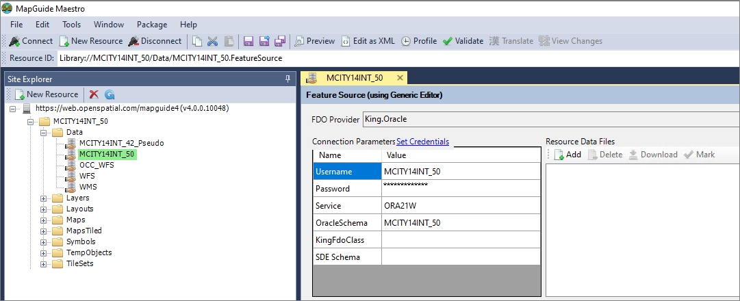
Fig: Redline Feature Source
To configure the setting the following steps can be followed:
- Navigate to Admin View > Site Administration > Configure Settings.
- Enter the correct URL where Variable is 'RL_FEATURE_SOURCE' to change it to the correct Redline Feature Source URL e.g. Library://MCITY14INT_50.Data/MCITY14INT_50.FeatureSource.
- To update the changes, click the Update button.
Redline Layer Prefix
The Redline Layer Prefix, for a new installation of enlighten, is set to NULL by default and configured using Enlighten Management Console. This setting should point to the folder location in the map definition for the Redline Layers.
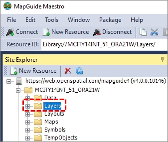
Fig: Redline Layer Prefix
To configure the setting the following steps can be followed:
- Navigate to Admin View > Site Administration > Configure Settings.
- Enter the correct URL where Variable is 'RL_LAYER_PREFIX' to change it to the correct Redline Layer Prefix URL e.g. Library://MCITY14INT_51_ORA21W/Layers/.
- To update the changes, click the Update button.
Redline Symbol Prefix
The Redline Symbol Prefix, for a new installation of enlighten, is set to NULL by default and configured using Enlighten Management Console. This setting should point to the URL for the website Redline Symbols folder location.
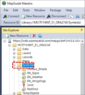
Fig: Redline Symbols Prefix
To configure the settings the following steps can be followed:
- Navigate to Admin View > Site Administration > Configure Settings.
- Enter the correct URL where Variable is 'RL_SYMBOL_PREFIX' to change it to the correct Redline Symbol Prefix URL e.g. Library://MCITY14INT_51_ORA21W/Symbols/.
- To update the changes, click the Update button.
Redline Symbol Default
The Redline Symbol Default setting can be set to point to an existing symbol in the Symbol Library that will be used when drawing redline point objects in the enlighten map.

Fig: Redline Symbol Default
To configure the settings the following steps can be followed:
- Navigate to Admin View > Site Administration > Configure Settings.
- Set the Value to a Symbol Name where Variable is 'RL_SYMBOL_DEFAULT' to change it to e.g. EN_Wingdings.SymbolLibrary/Circle6
- To update the changes, click the Update button.
Filter Redlines with Complete Status
This setting determines if redline objects, whose status is set to Complete, are filtered from being displayed on Redline layers on the map. By default, the value is set to NO meaning that the filter is not applied, and all redline objects with a Status of Complete will be displayed. Changes to this setting will be applied to all redline layer settings.
To configure the settings the following steps can be followed:
- Navigate to Admin View > Site Administration > Configure Settings.
- Set Value to YES where Variable is REDLINE_COMPLETE to apply the filter. By default, the variable is set to NO and the filter is not applied.
- To update the changes, click the Update button.
Redline Project Enabled
This setting is used to enable the Redline Project functionality for the enlighten website. If this setting is set to FALSE, none of the Redline Project functionality is available on the Manage Redline Objects task pane for all users.
To configure the settings the following steps can be followed:
- Navigate to Admin View > Site Administration > Configure Settings.
- Set Value to True where Variable is ENABLE_RL_PROJECT to enable the Redline Projects functionality.
- To update the changes, click the Update button.
Zoom Coordinates – Default projection
This setting specifies the projection that will be selected by default in the projection drop-down lists of the Zoom to Coordinates tool. The value to enter here is the SRID code of the desired projection from the SDO_COORD_REF_SYS table in Oracle.
To configure the settings the following steps can be followed:
- Navigate to Admin View > Site Administration > Configure Settings.
- Set Value to '82468' where Variable is 'DEFAULT_PROJ' to change the SRID to e.g. '82468'.
- To update the changes, click the Update button.
Zoom Coordinates – Projection List
This setting defines the projections available in the From Projection and To Projection drop-down lists when using the Zoom to Coordinates function on the enlighten toolbar. The values are entered as Spatial Reference System Identifiers (SRID) defining the coordinate system, map projection, and datum used to interpret geographic data. These values must exist in the SDO_COORD_REF_SYS table in Oracle to be able to transform the entered coordinate to the correct location on the enlighten map. When adding more than one SRID value to the list, they must be separated by a comma.
To configure the setting the following steps can be followed:
- Navigate to Admin View > Site Administration > Configure Settings.
- Enter a valid SRID value where Variable is PROJ_LIST. If more than one value is required, ensure the values are entered comma separated list of SRID values, for example 28355, 28354, 28356
- To update the changes, click the Update button.
Zoom Coordinates – Marker Symbol
This setting defines the symbol that will appear when the user selects the zoom coordinates tool. The symbol must be loaded into MapGuide Maestro.
To configure the settings the following steps can be followed:
- Navigate to Admin View > Site Administration > Configure Settings.
- Set Value to to point at a symbol definition of your choice e.g. 'Library://[MapServer]/Symbols/Enlighten.SymbolLibrary/Cross' where Variable is 'ZMCOORD_MARKER'
- To update the changes, click the Update button.
Zoom Coordinates - Marker Layer
This setting changes the temporary layer name used for redline zoom to coordinates. The default layer is Markers.
To configure the settings the following steps can be followed:
- Navigate to Admin View > Site Administration > Configure Settings.
- Set Value to 'Markers' where Variable is 'ZMCOORD_REDLINELAYER' to change the temporary layer name for redline zoom to coordinates.
- To update the changes, click the Update button.
Zoom Coordinates – Marker Symbol Size
This setting defines the size of the marker symbol that will appear when the user selects the Zoom Coordinates tool.
To configure the settings the following steps can be followed:
- Navigate to Admin View > Site Administration > Configure Settings.
- Set Value to '5' where Variable is 'ZMCOORD_MARKER_SIZE' to change the symbol size to e.g. '5'.
- To update the changes, click the Update button.
Point Selection Buffer on the map
This setting sets the map point selection buffer and only takes precedence if the map layout of the map definition is set to 0 or NULL.
Check the Point Selection Buffer setting in the Advanced Settings for the Map Layout which is configured using MapGuide Maestro. The default setting is (2) pixels, However, in the event this value is set to 0 or is left blank (NULL) , the database setting POINT_SEL_BUFFER will then take precedence.
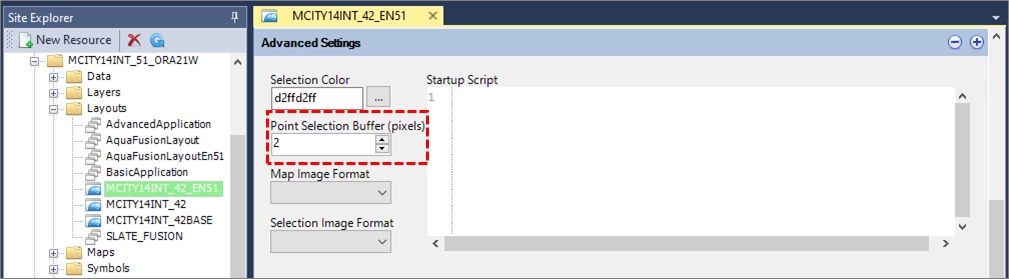
Fig: Map Layout for Map Definition as configured in MapGuide Maestro.
To configure this setting in the EN_SETTINGS if the Point Selection Buffer value in the Map Layout is either 0 or null, the following steps can be followed:
- Navigate to Admin View > Site Administration > Configure Settings.
- Set Value to '2' where Variable is 'POINT_SEL_BUFFER' to change the map point selection buffer set the Value to e.g. '2'.
- To update the changes, click the Update button.
Point Zoom Buffer
This setting sets the zoom buffer radius when when selecting point objects in the Search. Once the point object is found using the search criteria entered, if the Automatic Zoom tick-box is checked, the map is automatically zoomed around the point object. The default setting is (40) meters.
If the Automatic Zoom tick-box is not checked, and the Zoom Buffer value is set to NULL, no zooming to the point object occurs even though the object is selected in the map window. However, searches using point layers zooms correctly (setting POINT_ZOOM_BUFFER is applied) only if automatic zoom is not checked.
To configure the settings the following steps can be followed:
- Navigate to Admin View > Site Administration > Configure Settings.
- Set Value to '40' where Variable is 'POINT_ZOOM_BUFFER' to change the zoom buffer of a point object to 40 meters.
- If the map coordinate system is latitude/longitude this value should be much smaller as the unit will change to degrees and not retain the unit in meters. When the parameters are defined, click on the Update button to update the changes. If it fails, then it might be caused by the small value of the setting aspnet:MaxJsonDeserializerMembers in the web.config file. Then kindly increase this value to like 1200000 and try again (the site will be reloaded after this change).
Nearest Neighbour – Default Number
The nearest neighbours tool number defaults to ALL.
To configure the settings the following steps can be followed:
- Navigate to Admin View > Site Administration > Configure Settings.
- Set Value to '50' where Variable is 'NEIGHBOUR_NUMBER' to change it to e.g. '50 rows'.
- To update the changes, click the Update button.
Nearest Neighbour – Original
When finding the nearest neighbour, there is a tick-box at the bottom of the Nearest Neighbour Settings so that the selected feature is included in the selection set and is highlighted. The setting NEIGHBOUR_ORIGINAL sets the tick-box to be either checked/unchecked by default for new enlighten sessions. On installation, the default setting is 'No'. If the enlighten website is upgraded to the latest version, the existing setting is retained when applying any upgrade scripts.
To configure the settings the following steps can be followed:
- Navigate to Admin View > Site Administration > Configure Settings.
- Set Value to 'Yes' where Variable is 'NEIGHBOUR_ORIGINAL'.
- To update the changes, click the Update button.
Map Unit System
This setting specifies the Default Map Unit system (DEFAULT-INT, DEFAULT-US, ONLY-INT) that will be used when using any Measure or Buffer tools. The value to enter here is the Map Locale value of the desired map unit system.
To configure the settings the following steps can be followed:
- Navigate to Admin View > Site Administration > Configure Settings.
- Set Value to either 'DEFAULT-INT' ,'DEFAULT-US' or 'ONLY-INT' where Variable is 'MAP_UNIT_LOCALE' to change the Map unit system to e.g. 'ONLY-INT'.
- To update the changes, click the Update button.
Map Units
This setting sets the map display units. The default setting is (m) meters. The Map status bar displays the units set for the map, so if the units setting is updated to Feet, the Map Status Bar displays the map window dimensions in (ft).
To configure the settings the following steps can be followed:
- Navigate to Admin View > Site Administration > Configure Settings.
- Set Value to 'm' where Variable is 'UNITS' to change the map display unit to meters set the Value to e.g. 'm'.
- To change to another unit of distance, select an option from the drop-down list.
- To save the changes, click the Update button.
MapGuide Website URL
This setting defines the URL for the MapGuide Open Source software on the Server on which it is installed i.e. https://[server name]/mapguide4. This setting is typically setup when completing the initial Enlighten 5.1 installation using Enlighten Management Console where the Default value = "$IIS_Server$/mapguide4"
See topic called Map Configuration Settings in the Enlighten Installer documentation for more information.
To configure the settings the following steps can be followed:
- Navigate to Admin View > Site Administration > Configure Settings.
- Set Value to 'https://[server name]/mapguide4' where Variable is 'MGE_URL' to change the server address of where Map Guide Open Source is installed.
- To save the changes, click the Update button.
Spatial Outside Query
This setting sets the maximum number of objects returned when performing a spatial query using the outside spatial function. This refers to the Perform Spatial Functions  menu option found on the Advanced Toolbar and is specific to queries where the Outside spatial function is applied. The default setting is (100) objects which limits the number of resulting objects to 100.

Fig: Example of where the Outside spatial function is used and the limit applied.
To configure the settings the following steps can be followed:
- Navigate to Admin View > Site Administration > Configure Settings.
- Set Value to '100' where Variable is 'SPATIAL_OUTSIDE_MAX' to change the maximum number of objects set the Value to e.g. '100'.
- To update the changes, click the Update button.
MapGuide Resource Folder
This setting defines the folder within the MapGuide website where all temporary layers are automatically generated whenever Redline markups objects are drawn or Redline Project boundaries defined. This folder can be created using MapGuide Maestro to define a new web folder.
To configure the settings the following steps can be followed:
- Navigate to Admin View > Site Administration > Configure Settings.
- Set Value to the required folder location 'Library://[MapServer]/TempObjects/' where the Variable is 'RESOURCE_FOLDER' to change the folder location of where all temporary objects are automatically created.
- To update the changes, click the Update button.
Geo-scan Layer Name
This setting refers to the layer name(s) used to display the Geo-scan boundaries on the map. The database column where it is saved to is EN_SETTINGS.SETTING_VALUE and is currently VARCHAR(250), so multiple boundary layer-names can be configured up to the maximum column length limit of 250 characters. The default layer name assigned is 'GeoScan'.
The configured layer name is for the geo-scan boundary layer(s) only, and is used as the default layer when loading geo-scan boundaries on the enlighten map. If multiple boundary layers are configured in MGOS, then the value must be configured as a comma-delimited list of layer names. The layers referenced in the list must already exist in MGOS and have been published into enlighten via the Map Administration > Publish Layers and Forms process.
To configure the settings the following steps can be followed:
- Navigate to Admin View > Site Administration > Configure Settings.
- Set Value to GeoScan where Variable is 'GEOSCAN_LAYERNAME' to change the layer-name.
- To effect the changes, click the Update button.
Geo-scan Coordinate Name
The setting Geo-scan coordinate name setting refers to the coordinate system used for the scanned Engineering As-Built plans. If the Geo-scan Coordinate name is different to the Coordinate System defined for the enlighten base map in MGOS, the Geo-scan images are projected to the same coordinate system as the enlighten base map to ensure they are positioned in the correct location on the map. An example of a valid Geo-scan coordinate name is 'MGA-55' which is AutoCAD's projection code for the Map Grid of Australia Zone 55 using GDA 94 datum.
To configure the settings the following steps can be followed:
- Navigate to Admin View > Site Administration > Configure Settings.
- Set Value to MGA-55 where Variable is 'GEOSCAN_COORDNAME' to change the coordinate name.
- To effect the changes, click the Update button.
Viewer Application Definition
This setting refers to the location of the MapGuide Open Source application definition setup for all internal users of the enlighten website. The MapGuide Application Definition (AppDef) is the core configuration file used in MGOS and describes the layout, functionality and behavior of the web mapping application. The application tells MapGuide how the viewer should look, what tools, menus and layers are available to users.
To configure the settings the following steps can be followed:
- Navigate to Admin View > Site Administration > Configure Settings.
- For the Variable 'VIEWR_APP_DEFN' set the Value to point to the required Layout folder location, for example, Library://[MapServer]/Layouts/AquaFusionLayoutEn51.ApplicationDefinition
- To effect the changes, click the Update button.
External Viewer Application Definition
This setting refers to the location of the MapGuide Open Source application definition setup for all external users of the enlighten website. The MapGuide Application Definition (AppDef) is the core configuration file used in MGOS and describes the layout, functionality and behavior of the web mapping application. The application tells MapGuide how the viewer should look, what tools, menus and layers are available to users.
If, as and Administrator, you want to limit the layers available to external users who are perhaps only adding redline markups to certain utility layers, you can create a separate map definition file and use it exclusively for those users. This approach helps improve both performance and the user interface.
To configure the settings the following steps can be followed:
- Navigate to Admin View > Site Administration > Configure Settings.
- For the Variable 'EXT_VIEWR_APP_DEFN' set the Value to point to the required Layout folder location, for example, Library://[MapServer]/Layouts/AquaFusionLayoutEn51.ApplicationDefinition
- To effect the changes, click the Update button.
Preset Map Layers
The enlighten toolbar Layer Profiles contains an option for Preset Map Layers which uses database settings to build the list of available preset map layers. Please note that the visibility setting will still be effective.
To configure the settings the following steps can be followed:
- Navigate to Admin View > Site Administration > Configure Settings.
- Set Value to 'ZONING' where Variable is 'PRESET_LAYER_1' to set preset layer 1 to e.g 'Zoning'.
- Set Value to 'DENSITY' where Variable is 'PRESET_LAYER_2' to set preset layer 2 to e.g 'Density'.
- Set Value to 'BUILDING' where Variable is 'PRESET_LAYER_3' to set preset layer 3 to e.g 'Building'.
- Set Value to 'PARCEL' where Variable is 'PRESET_LAYER_4' to set preset layer 4 to e.g 'Parcel'.
- To update the changes, click the Update button.
Property System Matching
Below is a list of the Property System Matching Settings which can be updated via the Site Administrator functionality in Enlighten.
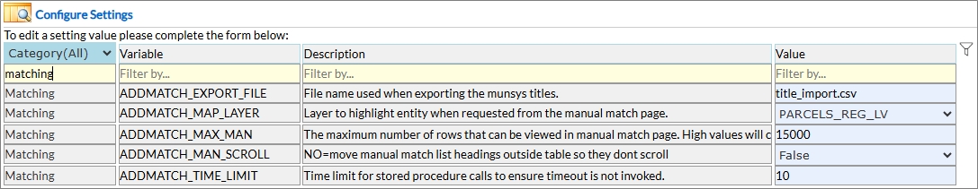
Fig: List of Property System Matching Settings
Address Matching – CSV Export File name
The CSV export process will use a default export file name when downloading to the user’s machine.
To configure the settings the following steps can be followed:
- Navigate to Admin View > Site Administration > Configure Settings.
- Set Value to 'yourCSV_file.csv' where Variable is 'ADDMATCH_EXPORT_FILE' to change the export file name.
- To update the changes, click the Update button.
Address Matching – Map Layer (Parcel)
The parcels layer name required when zooming to the map from the manual matching page.
To configure the settings the following steps can be followed:
- Navigate to Admin View > Site Administration > Configure Settings.
- Set Value to 'Parcels' where Variable is 'ADDMATCH_MAP_LAYER' to use manual matching.
- To update the changes, click the Update button.
Manual Matching list headings - Scrolling
This setting enables or disables scrolling on the manual match list headings. The default setting is disabled (FALSE) scrolling.
To configure the settings the following steps can be followed:
- Navigate to Admin View > Site Administration > Configure Settings.
- Set Value to 'FALSE' where Variable is 'ADDMATCH_MAN_SCROLL' to disable scrolling set the Value to e.g. 'False'.
- To update the changes, click the Update button.
Manual Matching – Maximum rows per page
This setting sets the maximum rows to display per page. The default setting is (4000) rows.
To configure the settings the following steps can be followed:
- Navigate to Admin View > Site Administration > Configure Settings.
- Set Value to '4000' where Variable is 'ADDMATCH_MAX_MAN' to change the maximum rows per page set the Value to e.g. '4000'.
- To update the changes, click the Update button.
Manual Matching – Limit stored procedures
This setting limits the number of simultaneous stored procedure calls. The default setting is (10) stored procedure calls.
To configure the settings the following steps can be followed:
- Navigate to Admin View > Site Administration > Configure Settings.
- Set Value to '10' where Variable is 'ADDMATCH_TIME_LIMIT' to change the number of simultaneous stored procedure calls set the Value to e.g. '10'.
- To update the changes, click the Update button.
 Network Trace Settings
Below is a list of the Network Trace Settings which can be updated via the Site Administrator functionality in Enlighten.

Fig: List of Network Trace Settings
Network Trace – Maximum Selection Count
This setting is used to set the maximum number of selections in the Network Trace results.
To configure the settings the following steps can be followed:
- Navigate to Admin View > Site Administration > Configure Settings.
- Set Value to '6000' where Variable is 'MAX_TRACE_SEL_COUNT' to set the number of selections in the Network Trace results.
- To update the changes, click the Update button.
Network Trace – Selection from Affected
The network trace can be made to select from all the affected or original layers.
To configure the settings the following steps can be followed:
- Navigate to Admin View > Site Administration > Configure Settings.
- Set Value to 'Affected Layers' where Variable is 'NETTRACE_AFFECTED' to select from all the affected layers.
- Affected layers are the output objects displayed, obtained from a Network Trace analysis. Alternatively the administrator can set the Value to 'Original Layers' where Variable is 'NETTRACE_AFFECTED' to select from all the default / original layers. The default layers are used by the Network Trace function to perform the analysis e.g. Input Data. Irrespective of this setting the Trace through feature will work even if the selection contains only 1 valid valve GID.
- To update the changes, click the Update button.
Network Trace – Using Relationships
Network trace should identify the table linkages and build the trace details into its temporary tables. If it cannot; then the trace will default to a layer maximum of 1000 keys per layer. This setting allows the choice to use Relationships in the latter default mode to join the services-parcels-properties to the affected pipes.
To configure the settings the following steps can be followed:
- Navigate to Admin View > Site Administration > Configure Settings.
- Set Value to 'YES' where Variable is 'NETTRACE_REL_PATHS' to enable the default number of keys per layer.
- To update the changes, click the Update button.
Network Trace – Service Connection Linking
Network Trace can be configured to link either Parcels, Buildings or Properties.
To configure the settings the following steps can be followed:
- Navigate to Admin View > Site Administration > Configure Settings.
- Set Value to either 'Parcel' ,'Building' or 'Property' where Variable is 'NETTRACE_SCLINK' to enable network trace to trace to the corresponding layer.
- To update the changes, click the Update button.
- Update the Parcel/Building/Property layer and Parcel Affected/Building Affected/Property Affected layer in Admin View > Map Administration > Network Trace page.
- Click the Save button.
Network Trace – Schema Type
This feature determines which sql scripts are used to link services to parcels/properties. There are four schema types the trace package recognizes to build links from services to parcels/properties. The three versions of the LandVic schema relate to Victorian customers. The Default schema should be applied to all other instances.
The default linkage path expects column PRCL_GID to exist in the service table for parcels. Similarly, it expects column PROP_GID to exist in the service table properties. It is therefore mandatory for these columns to exist to ensure that no issues arise when attempting to link parcels/properties.
To configure the settings the following steps can be followed:
- Navigate to Admin View > Site Administration > Configure Settings.
- Set Value to either 'Default' ,'DefaultVic' ,'LandVic' or 'LandVic1' where Variable is 'NETTRACE_SCHEMATYPE' to determine the sql to be used in linking services to Parcels or Properties.
- To update the changes, click the Update button.
Network Trace – Shutoff Block Trace
This feature can be switched on and allows for the availability to use pre-calculated shut-off block trace results for the network trace function.
To configure the settings the following steps can be followed:
- Navigate to Admin View > Site Administration > Configure Settings.
- Set Value to either 'TRUE' or 'FALSE' where Variable is 'SHUTOFF_BLOCK_TRACE'
- To update the changes, click the Update button.
Show Info Settings
Below is a list of the Show Info Settings which can be updated via the Site Administrator functionality in Enlighten.
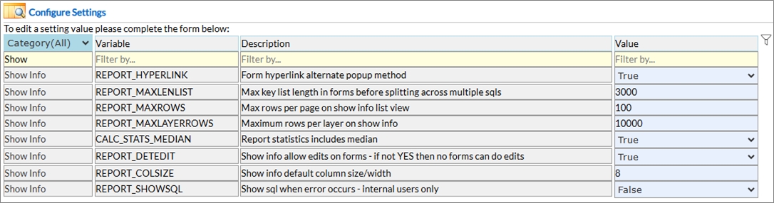
Fig: List of Show Info Settings
Show Info - text hyperlink
This setting essentially indicates if a certain text belonging to a particular column will appear as a hyperlink or plain text.
To configure the settings the following steps can be followed:
- Navigate to Admin View > Site Administration > Configure Settings.
- Set Value to 'TRUE' where Variable is 'REPORT_HYPERLINK' so the text appears as a hyperlink in the Show Info form pop-up. If set to 'FALSE' then it will appear as plain text.
- To update the changes, click the Update button.
Show Info - maximum key list length
The setting REPORT_MAXLENLIST is currently used in Show Info forms.
Form/Search queries set a maximum length for the key list, normally 3000 chars, leaving around 5000 chars for the rest of the query assuming SQL buffer is 8000 chars long. This should not be changed unless the buffer length changes.
SELECT * FROM SP_PARCEL WHERE GID IN (111,222,333)
The 3000 limit applies for 'GID IN (111,222,333)'.
To configure the settings the following steps can be followed:
- Navigate to Admin View > Site Administration > Configure Settings.
- Set Value to '3000' where Variable is 'REPORT_MAXLENLIST' to change the SQL maximum key length e.g. 3000 chars.
- To update the changes, click the Update button.
Show Info - maximum rows per page
The list-view defaults to maximum rows per page of 250. This value specified has to be above 20.
To configure the settings the following steps can be followed:
- Navigate to Admin View > Site Administration > Configure Settings.
- Set Value to '100' where Variable is 'REPORT_MAXROWS' to change it to e.g. 100 rows.
- To update the changes, click the Update button.
Show Info - maximum rows per layer
This value specifies the maximum records which can be returned per layer in the tree view. If no value is defined, then the system defaults to a value of 10 000 records per layer.
To configure the settings the following steps can be followed:
- Navigate to Admin View > Site Administration > Configure Settings.
- Set Value to '10 000' where Variable is 'REPORT_MAXLAYERROWS' to change it to e.g. 10 000 rows.
- To update the changes, click the Update button.
Show Info - Calc Stats Median
This setting indicates if the statistics would include the median or not.
To configure the settings the following steps can be followed:
- Navigate to Admin View > Site Administration > Configure Settings.
- Set Value to 'TRUE' where Variable is 'CALC_STATS_MEDIAN' to allow the system to include the Median in the report statistics.
- To update the changes, click the Update button.
Show Info - default column size for edit detail view
When a Show Info form is created or maintained, and the detail view has editable columns, if a maximum size is not set for a column then it will default to 10 when the form is saved.
To configure the settings the following steps can be followed:
- Navigate to Admin View > Site Administration > Configure Settings.
- Set Value to '20' where Variable is 'REPORT_COLSIZE' to change it to e.g. 20 columns.
- To update the changes, click the Update button.
Show Info - edit mode
Show Info detail view mode by default is set to display details only. If any editing is required, then Show Info itself needs to be given permission to allow users to edit columns.
To configure the settings the following steps can be followed:
- Navigate to Admin View > Site Administration > Configure Settings.
- Set Value to 'TRUE' where Variable is 'REPORT_DETEDIT' to enable editing.
- To update the changes, click the Update button.
Show Info - show SQL if an error occurs
If an error is encountered this setting will enable display of the SQL statement associated with the error which can be useful in identifying the cause of the error.
To configure the settings the following steps can be followed:
- Navigate to Admin View > Site Administration > Configure Settings.
- Set Value to 'YES' where Variable is 'REPORT_SHOWSQL' to show the SQL statement when errors occur.
- To update the changes, click the Update button.
Search Settings
Below is a list of the Search Settings which can be updated via the Site Administrator functionality in Enlighten.
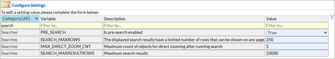
Fig: List of Search Settings
Searches - Pre-Search
This setting enables or disables pre-search. The default setting is enabled (TRUE) pre-search.
To configure the settings the following steps can be followed:
- Navigate to Admin View > Site Administration > Configure Settings.
- Set Value to 'TRUE' where Variable is 'PRE_SEARCH' to enable pre-search set the Value to e.g. 'TRUE' rows
- To update the changes, click the Update button.
Searches – Maximum rows per page
The displayed search results have a limited number of rows that can be shown on any page.
To configure the settings the following steps can be followed:
- Navigate to Admin View > Site Administration > Configure Settings.
- Set Value to '200' where Variable is 'SEARCH_MAXROWS' to change it to e.g. '200' rows
- To update the changes, click the Update button.
Searches - Maximum Objects for direct zoom
This setting limits the number of objects for direct zoom. The default setting is (10) objects.
To configure the settings the following steps can be followed:
- Navigate to Admin View > Site Administration > Configure Settings.
- Set Value to '10' where Variable is 'MAX_DIRECT_ZOOM_CNT' to change the number of object direct zoom set the Value to e.g. '10' objects
- To update the changes, click the Update button.
Searches - Maximum Search records returned
This setting limits the search records retrieved to a maximum of 100 000 records. This can be altered depending on the business needs.
To configure the settings the following steps can be followed:
- Navigate to Admin View > Site Administration > Configure Settings.
- Set Value to 'x' where Variable is 'SEARCH_MAXRESULTROWS' to change the number of records that can be returned e.g. '100 000' records
- To update the changes, click the Update button.
Shut Off Report Settings
Below is a list of the Shutoff Settings which can be updated via the Site Administrator functionality in Enlighten.
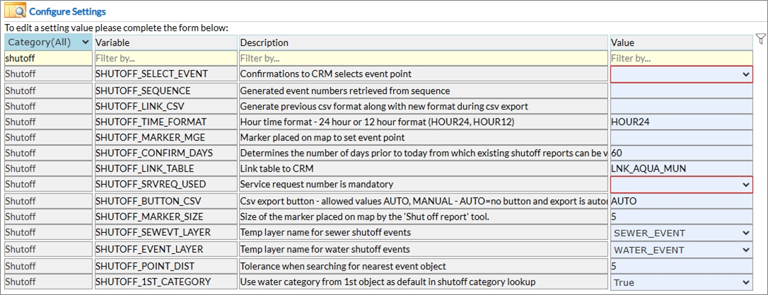
Fig: List of Shutoff Settings
Shut Off Reports – Select Event
This setting setting controls whether the shutoff event object is also selected when the user chooses a shutoff job in the shutoff confirmations page. If the value is set to True then the shutoff event layer object is included in the map selections.
To configure the settings the following steps can be followed:
- Navigate to Admin View > Site Administration > Configure Settings.
- Set Value to 'True' where Variable is 'SHUTOFF_SELECT_EVENT' to include the shutoff event layer object in the map selections.
- To update the changes, click the Update button.
Shut Off Reports – Sequence
This setting enables the user to have all shutoffs following the same sequence and utilized for the Shut Off Job Id. For WATER the sequence would use ENS_WATREPORT_ID and NULL would use ENS_SEWEREPORT_ID.
To configure the settings the following steps can be followed:
- Navigate to Admin View > Site Administration > Configure Settings.
- Set Value to 'WATER' where Variable is 'SHUTOFF_SEQUENCE' to allow all sequences to follow one sequence (Water)
- To update the changes, click the Update button.
Shut Off Reports – Link CSV Format
This setting XXX.
To configure the settings the following steps can be followed:
- Navigate to Admin View > Site Administration > Configure Settings.
- Set Value to XXX where Variable is 'SHUTOFF_LINK_CSV' to XXX
- To update the changes, click the Update button.
Shut Off Reports – CSV Export Button
This setting enables or disables the CSV export button. The default setting is disabled (Auto) which hides the CSV button and automatically saves shut off reports to csv.
To configure the settings the following steps can be followed:
- Navigate to Admin View > Site Administration > Configure Settings.
- Set Value to 'AUTO' where Variable is 'SHUTOFF_BUTTON_CSV' to enable auto CSV export set the Value to e.g. 'AUTO'.
- To update the changes, click the Update button.
Shut Off Reports – Hour time format
This setting changes the hour time format in shutoff events. The default hour time format is (HOUR24).
To configure the settings the following steps can be followed:
- Navigate to Admin View > Site Administration > Configure Settings.
- Set Value to 'HOUR24' where Variable is 'SHUTOFF_TIME_FORMAT' to set the Value to e.g. '24-hour ' Format
- To update the changes, click the Update button.
Shut Off Reports – Number of Days before shutoff reports can be viewed
When shutoff reports are created this setting determines the number of days prior to 'today' from which existing shutoff reports can be viewed.
To configure the settings the following steps can be followed:
- Navigate to Admin View > Site Administration > Configure Settings.
- Set Value to '1' where Variable is 'SHUTOFF_CONFIRM_DAYS' to change the number of days set the Value to e.g. '1' day
- To update the changes, click the Update button.
Shut Off Reports – Marker Symbol
Specify which symbol to be used when marking event point on the map.
To configure the settings the following steps can be followed:
- Navigate to Admin View > Site Administration > Configure Settings.
- Set Value to 'Library://GVW_EN4/Symbols/Enlighten.SymbolLibrary/Cross' where Variable is 'SHUTOFF_MARKER_MGE' to change it to e.g. the cross symbol.
- To update the changes, click the Update button.
Shut Off Reports – Marker Symbol Size
To set the size assigned to the marker symbol.
To configure the settings the following steps can be followed:
- Navigate to Admin View > Site Administration > Configure Settings.
- Set Value to '20' where Variable is 'SHUTOFF_MARKER_SIZE' to change the symbol size to e.g. '20'
- To update the changes, click the Update button.
Shut Off Reports – Point Tolerance
When a shut off event is clicked on the map there is a limit to the distance in which a geo-search is made to locate the pipe or node. The default is usually set to 3 meters.
To configure the settings the following steps can be followed:
- Navigate to Admin View > Site Administration > Configure Settings.
- Set Value to '5' where Variable is 'SHUTOFF_POINT_DIST' to change the distance to e.g. '5' meters
- To update the changes, click the Update button.
Shut Off Reports – Water Shutoff Events temp layer
This setting changes the temporary layer name used for water shutoff events. The default temporary layer is 'Water_Shut_Off_Event'.
To configure the settings the following steps can be followed:
- Navigate to Admin View > Site Administration > Configure Settings.
- Set Value to 'Water_Shut_Off_Event' where Variable is 'SHUTOFF_EVENT_LAYER' to change the temporary layer name for water shutoff events set the Value to e.g. 'Water_Shut_Off_Event'
- To update the changes, click the Update button.
Shut Off Reports – Sewer Shut Off Events temp layer
This setting changes the temporary layer name used for sewer shutoff events. The default temporary layer is 'Sewer_Shut_Off_Event'.
To configure the settings the following steps can be followed:
- Navigate to Admin View > Site Administration > Configure Settings.
- Set Value to 'Sewer_Shut_Off_Event' where Variable is 'SHUTOFF_SEWEVT_LAYER' to change the temporary layer name for sewer shutoff events set the Value to e.g. 'Sewer_Shut_Off_Event'
- To update the changes, click the Update button.
Shut Off Reports – 1st Object as a category lookup
This setting enables or disables the use of the 1st object as a category lookup. The default setting is enabled (TRUE).
To configure the settings the following steps can be followed:
- Navigate to Admin View > Site Administration > Configure Settings.
- Set Value to 'TRUE' where Variable is 'SHUTOFF_1ST_CATEGORY' to enable the use of the 1st object as a category lookup set the Value to e.g. 'TRUE'
- To update the changes, click the Update button.
Shut Off Reports – Mandatory Service Request Number
This setting enables or disables mandatory service request numbers. The default setting is enabled (TRUE).
To configure the settings the following steps can be followed:
- Navigate to Admin View > Site Administration > Configure Settings.
- Set Value to 'TRUE' where Variable is 'SHUTOFF_SRVREQ_USED' to enable mandatory service request numbers set the Value to e.g. 'TRUE'.
- To update the changes, click the Update button.
Shut Off Reports – CRM Link Table
This setting sets the CRM link table. The default setting is NULL where no link has been defined.
To configure the settings the following steps can be followed:
- Navigate to Admin View > Site Administration > Configure Settings.
- Set Value to 'LNK_AQUA_MUN' where Variable is 'SHUTOFF_LINK_TABLE' to set the CRM link table set the Value to e.g. 'LNK_AQUA_MUN'.
- To update the changes, click the Update button.
Site Security
Within the Site Security setting, there is a MOB_USER variable. When this drop-down is set to Mobile, then this is an indication that the user is a mobile user. When this drop-down is set to None, then this is an indication that the user is a web user.
Configure Network Trace Settings
Configure Network Trace Settings gives an overview of the default water pipe network trace settings, validation of the water pipe network trace settings and the option to customize the water pipe network trace settings to your organisations needs.
To Configure Network Trace Settings the following steps can be followed:
- Navigate to Admin View > Site Administration > Configure Network Trace Settings.
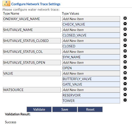
Fig: Configure Network Trace Settings - To validate the default water pipe network trace settings, select the Validate button.
- To edit the default water pipe network trace settings, select add
 or remove
  Type Values and select the Save button, then validate the new water pipe network trace settings by selecting the Validate button.
 - To remove the first Type Value belonging to a Type Name category, the user should click within the text box and manually delete the text. Once this is done then the user can then click the Save Button.
- To set the water pipe network trace settings back to the default water pipe network trace settings select the Reset button.
 Plot Engine Status
Plot Engines Status gives an overview of all the registered plot engines in your organization. Plot engine Uptime, Status and Current Job time can be seen here.
Plot engines can also be Registered and Unregistered.
To Configure Settings the following steps can be followed:
- Navigate to Admin View > Site Administration > Plot Engine Status.
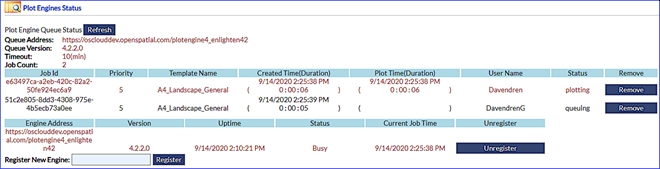
Fig: Plot Engine Status
Information pertaining to the Job will be displayed when a plot has been requested, which will adequately advise the administrator on particulars regarding the plot jobs. The administrator will easily be able to see the Job Id which is generated, the Template Name in use to generated the plot as well as the Time Duration. Information such as the User Name of the individual who logged in and requested the plot will be available as well as the current Status of the plot.
There is a distinction that can be found in the status field, which is plotting and queuing. Plotting refers to the jobs which are currently being plotted at the present moment and therefore is removed from the queuing field. Items found in the queuing field are multiple jobs pending which are in the queue to be plotted when the prescribed plot engine is available again.
 Active Users
Active Users gives an overview of all the user activity in your organization. User information, connection times, Browser and Actions can be seen here. The option to terminate a user's session as an Administrator user has been added as a configuration setting to the EN_SETTINGS table called ADMIN_LOGOUT_USERS.
To view Active Users the following steps can be followed:
- Navigate to Admin View > Site Administration > Active Users.
- Select a user to see the specific connection activities of the selected user.
- Click on the user's name so that their session details are displayed.
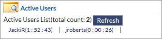
Fig: Active UsersDetailed connection information of the selected user will be shown.

Fig: Single Active User - Select Show Actions to view detailed information on the user`s activity in enlighten.

Fig: Show Actions - To refresh the list of current active users, click the Refresh button.
Terminating a User’s Session
This function allows for instances when there is a user session which is dormant or exists idle in the system. The Terminate function allows the admin to Terminate the session which would simultaneously log the user out instantly.
The option to terminate a user's session as an Administrator user has been added as a configuration setting to the EN_SETTINGS table. The setting ADMIN_LOGOUT_USERS must be set to True before the Administrator user can select the Terminate Session option.
To ensure the Administrator can terminate user's session, check the following setting in Site Administration > Configure Settings:
- Navigate to Admin View > Site Administration > Configure Settings.
- Filter the list of settings by typing the variable ADMIN_LOGOUT_USERS in the heading for Variables.

Fig: Check Configuration Setting - Ensure the Value is set to TRUE.
Fig: Set Configuration Setting value to TRUE
To Terminate a User Session the user must:
- Navigate to Admin View > Site Administration > Configure Settings.
Fig: Active Users Page - Click on the User to be Terminated and then click on the Terminate Session button.
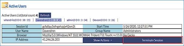
Fig: Terminate Session Button - Enter a Reason for Terminating the user’s session.
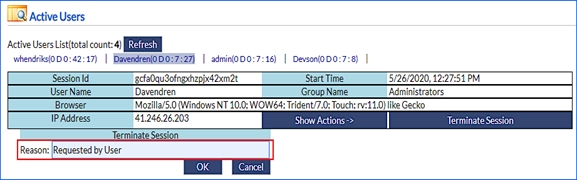
Fig: Reason for Terminating Session - Click on OK.
A message indicating the session has been terminated successfully will be displayed.
- Click on Refresh.

Fig: Refresh Active Users pageWhen the administrator clicks out of the current page and navigates back in, then the user’s session would be removed from the Active Users screen.