ACDC Desktop Menu and Toolbar Functions
The ACDC installation adds the ACDC and Configurator toolbars and the ACDC Ribbon Toolbar to the AutoCAD product on which ACDC Desktop was installed. The ACDC Configuration toolbar contains tools specific to the configuration process. The ACDC toolbar contains tools used during the validation and conversion processes. Details of these tool bars are contained below.
The ACDC Ribbon Toolbar contains all of the ACDC tools. Should the ribbon and toolbars fail to display after installation, type the command ACDCMENULOAD at the command line.
ACDC Toolbar

Fig: ACDC Toolbar.
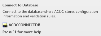
 Connect to Database - Connects to the database where ACDC stores configuration information and validation rules.
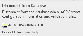
 Disconnect from Database - Disconnect from the database where ACDC stores configuration information and validation rules.
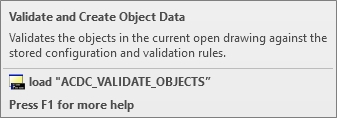
 Validate and Create Object Data - Validates the objects in the current open drawing against the stored configuration and validation rules.
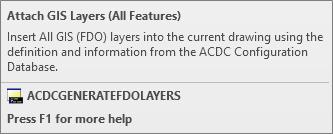
 Attach GIS Layers (All Features) - Insert All GIS (FDO) layers into the current drawing using the definition and information from the ACDC Configuration Database.
 Attach GIS Layers (Related Features) - Insert only matching GIS (FDO) layers based on entities in the current drawing using the definition and information from the ACDC Configuration Database.
 Convert to GIS - Converts the validated AutoCAD objects and object data to the feature objects of the target database.
 Post to GIS - Checks in all features and saves changes to the feature source.
 Export Objects to CZML - Exports selected Validated Sanitary Sewer and Storm Drainage pipes and/or nodes to Open Source CZML format.
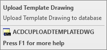
 Upload Template Drawing - Uploads the Template Drawing to the database.
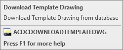
 Download Template Drawing - Downloads the Template Drawing from the database.
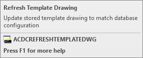
 Refresh Template Drawing - Update stored Template Drawing to match database configuration.
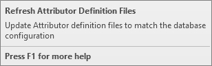
 Refresh Attributor Definition Files - Update Attributor Definition Files to match database configuration.
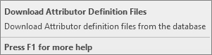
 Download Attributor Definition Files - Download Attributor Definition Files from database.
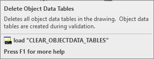
 Delete Object Data Tables - Deletes all object data tables in the drawing. Object data tables are created during validation.
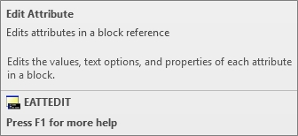
 Edit Attribute - Edits the values, text options, and properties of each attribute in a block.
ACDC Configuration Toolbar
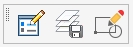
Fig: ACDC Configuration Toolbar.
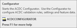
 Configurator - Starts the ACDC Configurator. Use the ‘Configurator’ to configure ACDC validation rules, settings, and feature data.
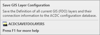
 Save GIS Layer Configuration - Saves the definition of all current GIS (FDO) layers and their connection information to the ACDC configuration database.
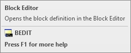
Block Editor - Opens the block definition in the AutoCAD Block Editor.
ACDC Ribbon Toolbar
The commands on the ACDC Ribbon Toolbar are the same commands which appear on the ACDC Toolbar and the ACDC Configuration Toolbar with the exception that the ACDC ribbon toolbar and menu include the ACDC Online Help and About ACDC..

Fig: ACDC Ribbon Toolbar.
 ACDC Online Help - Navigates the user to Open Spatial's online ACDC Desktop User Manual which is opened in the default browser window.
 About ACDC - Displays the About ACDC dialog.

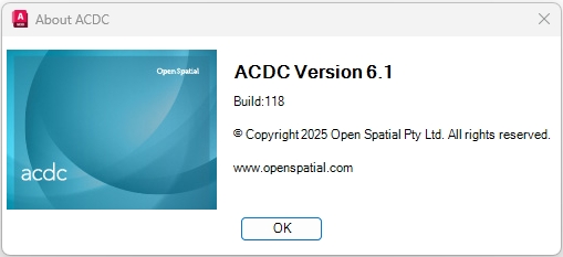
Fig: About ACDC dialog.
ACDC Menu
The commands on the ACDC Menu are the same commands which appear on the ACDC Ribbon, ACDC Toolbar and the ACDC Configuration Toolbar with the exception that the ACDC menu and ribbon toolbar include the ACDC Online Help and About ACDC.
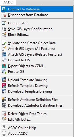
Fig: ACDC Menu.
ACDC Drawing Templates
A template drawing in ACDC is a predefined CAD file that encapsulates standardised configuration data, including attribute blocks, layers, styles, coordinate system, drawing units and layout settings, used as a baseline for generating new as-constructed drawings. ACDC Drawing Templates are created per organisation to ensure external and internal developers conform to the specified industry standards and organisation requirements when capturing as-constructed data.
The predefined layers in the ACDC template are primarily used to draw specific asset types from the Attributor menu options with their required attribute information. The correct predefined layer MUST be used when drawing the desired asset type. For example, the WPIPE layer would be used to draw water pipes. This not only maintains a simple color theme for each asset but it is essential in The Configuration Process.
Predefined attributed blocks in the ACDC template can be attached to object entities that are drawn in AutoCAD. For example, when a water pipe attribute block is attached to a polyline drawing (representing a water pipe), after validation and conversion of that polyline in ACDC, the polyline will possess the attributes of the associated water pipe attribute block.
- Automated tools exist to mass create and define attributed blocks from Excel spreadsheets.
- AutoCAD Fields can be used to populate default values into block tags.
- When a block is inserted into a drawing, you can specify attribute values on the command line OR in a dialog box. By default, you specify the attribute values on the command line. To use a dialog box, change the value of the ATTDIA system variable to 1 by typing ATTDIA on the command line and changing its value to 1. Change it back to 0 to use the command line again.
The organization's Drawing Template can be saved to and retrieved from the database. New functionality has been added to the ACDC Desktop Toolbar and ACDC Desktop Menu to upload, download and refresh the stored drawing template in the database and the database configurations.
Upload Template Drawing
Once the current drawing is correctly configured and ready to use as the basic template drawing it can be uploaded to the database to replace the existing template drawing, if it exists, or to create a new drawing template if there is no existing template saved. This DWG file is saved as a BLOB file where it can be downloaded using the Download Manually Configured Template.
If you elect to upload a Drawing Template File it will use the template layers, attribute blocks and their block definitions defined in the template drawing file to update any existing configuration in the database, and it will overwrite any existing drawing template file saved as a BLOB object in the database. For this reason a message is displayed on the command line before the user proceeds with the upload.
To upload the current drawing as a new drawing template to the database, complete the following steps:
- Ensure all the necessary blocks and their respective attributes and layers are saved the current drawing.
- Connect to the required database.
- On the ACDC Toolbar select the Upload Template Drawing icon or select the menu option Upload Template Drawing.
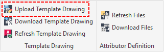
Fig: Menu item for Upload Template Drawing - At the command prompt the following message is displayed:
Are you sure you want to upload template drawing? This will replace any existing template drawing in the database? [Yes No]- Select Yes to proceed to overwrite any database configurations and drawing template file.
- Select No to cancel the operation.

Fig: Confirmation Message when uploading a Template Drawing - After selecting Yes the command line prompts the user to Update Blocks? [Yes/No].
- Selecting Yes will update any existing blocks configured in the database and add new ones.
- Selecting No does not update the blocks.

Fig: Prompt to Update Blocks - After the block update process, the user is prompted to Update layer colors? [Yes/No].
- Selecting Yes will update the layer colors configured in the database.
- Selecting No does not update the layer colors.

Fig: Prompt to Update Layer Colors - After the update of the layer color process, the user is prompted to Update attribute display order? [Yes/No].
- Selecting Yes will update the attribute display order configured in the database.
- Selecting No does not update the layer colors.

Fig: Prompt to Update Attribute Display Order - After the update of the attribute display order, the user is prompted to Update template? [Yes/No].
- Selecting Yes will update the template drawing configured in the database.
- Selecting No does not update the template drawing.

Fig: Prompt to Update Template Drawing - On completion of the template update the command line feedback indicates the template drawing was successfully updated.

Fig: Prompt indicating Template was successfully updated
Download Template Drawing
The Download Template Drawing function enables users to download a template drawing from the database in one of two ways:
- Manually Configure: Downloads a previously uploaded and saved template drawing (.DWG) from the database.
- Auto Configured: Automatically generates a template drawing based on the current configuration stored in the database.
This feature supports pre-configured attribute blocks, layers, and style standards defined using ACDC’s Configurator. When using the Auto Configured option, the template is generated dynamically according to the saved database settings.
When downloading either an Auto Configured or Manually Configured template, users are prompted to select the desired file format:
- 1=DWG: Typically used for active design work and contains drawing geometry and project-specific data.
- 2=DWT: A template file that stores predefined settings, styles, and standard content for use when creating new drawings.
- 3=BOTH: Both the .DWG and .DWT files are downloaded.
To download the template drawing, follow the steps below:
- Close all drawings in your CAD session.
- Connect to the required database.
- On the ACDC Toolbar select the Download Template Drawing icon or select the menu option Download Template Drawing.
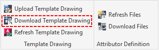
Fig: Menu item for Download Template Drawing - The user is prompted to select the template to download, where the user must enter option 1 or 2:
- 1. Auto Configured (AUTO_TEMPLATE.dwt)
- 2. Manually Configured template ([drawing_name].dwg)

Fig: Select Template to download - When downloading either the Auto Configured or Manually Configured template, users are further prompted to select the desired file format, where the 1-DWG format is the default.
Enter the desired number of 1, 2 or 3:- Download format [1=DWG 2=DWT 3=BOTH] <1-DWG>:

Fig: Select File Format options to download - Upon selecting the required file format the user is then prompted to select the folder location for the downloaded files in the File Explorer window.
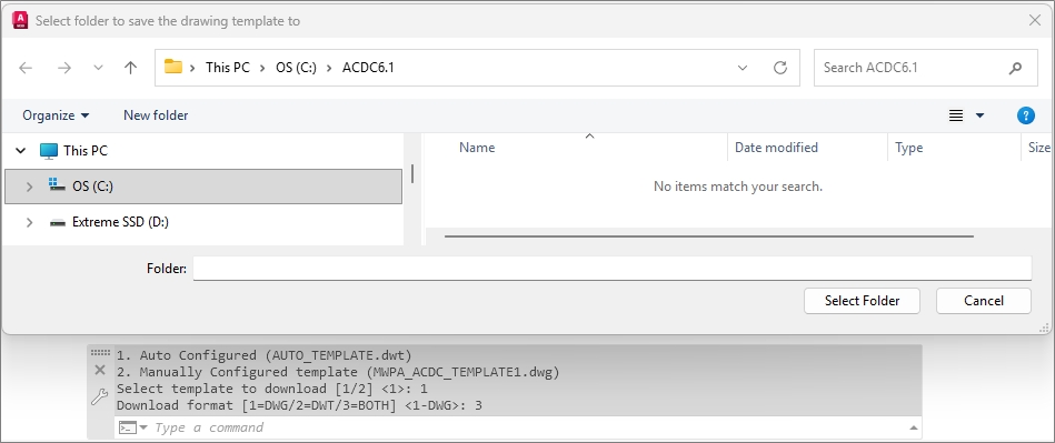
Fig: Select folder location - A confirmation message of the file names and folder location is displayed in the command prompt once the files are successfully downloaded

Fig: Successful file download prompt - In the event the user selects to download the Auto Configured Template, but the drawing template does not exist in the database, the user will be presented with an error message on the command line similar to the message below.

Fig: Error Message when no Auto Template available for download
Refresh Template Drawing
In the event any new block symbols, or changes to existing block symbols and their associated block definitions, layers and drawing settings, the user has the option to Refresh the Template Drawing which replaces the configured block symbols and their block definitions in the database with those in the template drawing, and to replace the template drawing in the database with the template used to refresh.
As part on the ACDC Desktop installation, default block geometries are supplied in the Symbols folders for both Feet and Meters. In the event there are blocks in the current template drawing open in AutoCAD that do not have block geometries defined, when electing to Refresh the Template Drawing the user will be prompted to generate missing block geometries.
Should the user select YES to this step, if any block with missing geometry be assigned the geometry of the the default POINT.DWG, LINE.DWG or POLYGON.DWG depending on their object type.
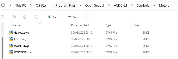
Fig: Default Block Geometry for Point, Line and Polygon blocks
The Drawing Template in the database can be refreshed or overwritten with the current drawing template in the CAD session by following these steps:
- Close all drawings in your current AutoCAD session and only open the drawing being used to refresh the template drawing.
- Connect to the required database.
- On the ACDC Toolbar select the Refresh Template Drawing icon or select the menu option Refresh Template Drawing.
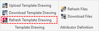
Fig: Menu item for Refresh Template Drawing - At the command prompt the command line prompts the user with the message:
Are you sure you want to replace the template drawing and block symbols in the database? [Yes / No].- Entering Yes proceeds to replace the template drawing and the block symbols in the database with those in the current drawing file.
- Entering No exits the command.

Fig: Confirmation Message when refreshing a Template Drawing - Should the user select Yes to the step above, they are then presented with the following message on the command line:
Do you want to generate missing block geometries? [Yes / No]- Entering Yes proceeds to generate any missing block geometries.
- Entering No skips the generation of missing block geometries.

Fig: Confirmation Message to generate missing block geometries
NOTE: If there is a block which does not have a block geometry (block symbol), based on the type of object type associated to the block a default block geometry will be assigned. - The command line displays feedback on the refresh process where any existing blocks and layers in the database are deleted and then refreshed referencing the blocks in the open AutoCAD drawing, for example:
Missing block geometries generated
- WSPEC_VALVE [POINT]
- WSPEC_PUMP_STATION_SITE [POLYGON]
- WSPEC_PRESSURE_MAIN [LINE] - After updating of blocks the upload process prompts the user to select the Template Measurement [English/Metric] and to Enter a template description where the blocks are further processed.

Fig: Enter Metric and template description during the Refresh process - On completion the feedback on the command line advises if the Template Drawing has been successfully updated.

Fig: Command line feedback on successful Template Drawing update
Attributor Definition Files
Open Spatial’s Attributor is a separate, downloadable plugin for AutoCAD and BricsCAD and forms part of the ACDC Suite. It enables the configuration and use of drop-down lists on CAD block attribute tags, improving data capture while ensuring consistency, standardization, and accuracy. Configurations created using the ACDC Desktop Configurator can be exported as Attributor Definition files, which are used to define mandatory attribute tags for each block and to specify drop-down lookup lists containing standardized selection options.
Refresh Attributor Definition Files
The Attributor Definition files can be refreshed to align with the database configuration stored in the OSX_AP_SETTINGS table. This process should be completed before downloading the Attributor files by following the steps below:
- On the ACDC Toolbar select the Refresh Attributor Definition Files icon or select the menu option Refresh Files.
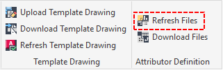
Fig: Menu item to Refresh Attributor definition files - At the command prompt the confirmation message is displayed:

Fig: Confirmation Message when Confirmation Message when refreshing the Attributor Definition files
Download Attributor Definition Files
The Attributor Definition files forming part of Open Spatial's Attributor plugin for AutoCAD and BricsCAD, consists of two files called OSBLOCK_DEF.txt and OSATTR_DOMAIN.txt, and determine the block definitions, attributes and lookup tables which are referenced in the Open Spatial's Attributor plugin menu items. These two files are generated from the configuration settings in the ACDC database and should be refreshed before being generated.
The files can be downloaded as text files by following these steps:
- On the ACDC Toolbar select the Download Attributor Definition Files icon or select the menu option Refresh Files.
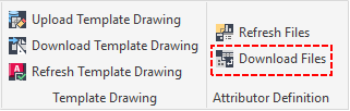
Fig: Menu item to Download Attributor definition files - At the command prompt the following message is displayed indicating the contents of the configuration file is being read.

Fig: Message advising that the configuration file is being read - The Select folder to save attribute definition files to dialog box is immediately opened where you need to select a temporary folder for the Attributor Definition files to be downloaded to, for example C:\ACDC6.1.
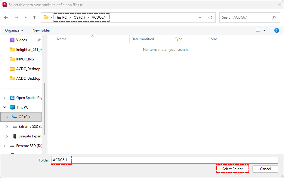
Fig: Select folder for download files - Once the Attributor Definition files are successfully downloaded and saved to the nominated folder, a confirmation message is displayed at the command line.

Fig: Confirmation Message indicating files are successfully downloaded - In an explorer window, navigate to the nominated folder to view the two Attributor Definition files.
Please consult Open Spatial's Attributor installation notes to determine where these two downloaded files should be copied to on the user's workstation. For example, if you have Attributor 2.0 installed as a plugin for Autodesk, the two text files should be copied to
C:\Users\[username]\AppData\Roaming\Autodesk\ApplicationPlugins\Attributor.bundle\Application\Resources
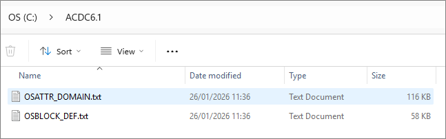
Fig: View saved Attribute Definition files- The file OSATTR_DOMAIN.txt contains the drop-down lists of mandatory values for blocks and the block attribute tags.
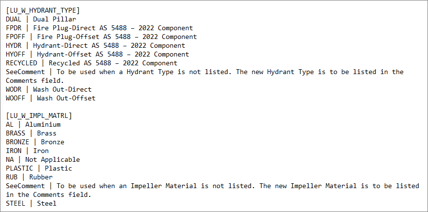
- The file OSBLOCK_DEF.txt contains the mandatory block attribute tags per block name.
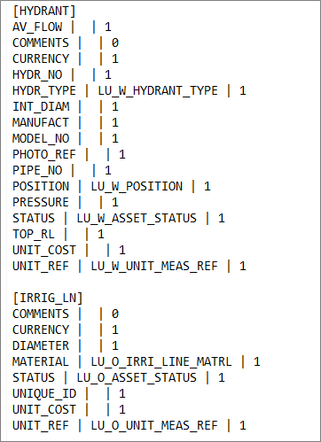
- The file OSATTR_DOMAIN.txt contains the drop-down lists of mandatory values for blocks and the block attribute tags.
Export to CZML File Format
The option to Export Objects to CZML allows the user to select validated sewer or drainage objects in the AutoCAD drawing to export to an Open Source CZML file format. The CZMLDef.ini configuration file, installed in the default Installation location C:\Program File\Open Spatial\ACDC 6.0, is a definition file which stores all the parameters and settings that are required to interpret the data to be converted to a CZML file.
The configuration file is also used to specify which attributes to display, to set the color and opacity for solid filled objects, to set line widths and colors for line and polyline objects, and to define which CZML object type and color to represent node type objects.
CZML is a JSON format for describing graphical data in a 3D context or primarily for display Digital Twin environments such as Cesium or Terria.io. These 3D data files can then be displayed in Digital Twin Environments such as Cesium virtual globe or Terria.io where global 3D terrain, imagery and building infrastructure are used to provide full 3D geo-spatial visualization in context and integrated with active environments.
The resultant CZML file contains a single JSON array for each object selected in the drawing, where each object-literal element in the array is a CZML Packet. A CZML Packet describes the graphical properties for a single object in the scene, such as a sewer node and pipe.
CZML Export configuration file
The configuration file CZMLDef.ini is installed as part of the ACDC Application and stores all the parameters and settings required to interpret data to be “converted” to a CZML file. The default configuration file is populated with “example” parameters. It is recommended that the .ini file be copied to another folder location before it is edited.
When defining a color to use for the CZML object, an on-line RGBA color picker can be used to get the Red Green Blue Alpha values, and these are saved as values in the following format [255,255,255,255]. The Alpha parameter is a number between 0 (fully transparent) and 255 (fully opaque).
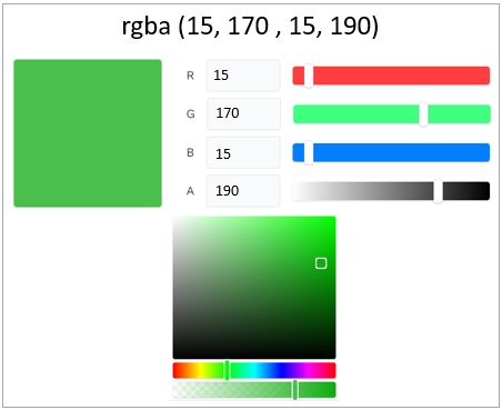
Fig: RGBA Color Picker.
Example of configuration file for Stormwater Pipes
The following parameters, based on D-SPEC digital data specification, are required to export Stormwater gravity pipes to CZML format:
- ID_DESCRIPTION: Indicates the object is a pipe i.e. Pipe.
- NAME_DESCRIPTION: Populates the Name variable in the CZML packet header i.e. Stormwater Pipe Gravity.
- LAYER_NAMES: Layer name on which the object is drawn in AutoCAD i.e. DSPEC_new_PIPES.
- LAYER_OBJECT_TYPE: The AutoCAD object type used to represent the pipe i.e. LINE.
- OD_TABLENAME: Object Data Table Name i.e. DSPEC_PIPES.
- START_HEIGHT: The start invert level from the upstream start invert level column i.e. US_IL.
- END_HEIGHT: The end invert level from the downstream end invert level column i.e. DS_IL.
- PIPE_DIA: The pipe diameter from the pipe width column i.e. DIA_WIDTH.
- COLOR_RGBA: Sets the color used to represent the drainage pipe using RGBA format [255,255,255,255] i.e. 0,255,0,255.
- ATTRIBUTE_COLUMN_NAMES: List of additional columns to be included in export file as defined in the Object Data table i.e. PLAN_NO, STAGE_NO, US_IL, DS_IL.
- ATTRIBUTE_COLUMN_DESCRIPTIONS: List of additional column descriptions to be included in export file as defined in the Object Data table i.e. Plan No, Stage No, Upstream Invert Level, Downstream Invert Level.
- CZML_OUTPUT_TYPE: The CZML Object type used to represent the object. Stormwater Gravity Pipes can be represented as a PIPEVOLUME type.
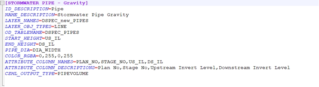
Fig: Example of Export Definition file for Stormwater Gravity Pipe.
Example of configuration file for Stormwater Pit Node
The following parameters, based on D-SPEC digital data specification, are required to export Stormwater Pit nodes to CZML format:
- ID_DESCRIPTION: Indicates the object is a Stormwater Pit node i.e. Node.
- NAME_DESCRIPTION: Populates the Name variable in the CZML packet header i.e. Pit.
- LAYER_NAMES: Layer name on which the object is drawn in AutoCAD i.e. DSPEC_new_PITS.
- LAYER_OBJECT_TYPE: The AutoCAD object type used to represent the node i.e. INSERT.
- OD_TABLENAME: Object Data Table Name i.e. DSPEC_PITS.
- NODE_HEIGHT: The node height from the Frame Start Level column i.e. FSL.
- NODE_DEPTH: The Node Depth value from the depth column i.e. DEPTH.
- COLOR_RGBA: Sets the color used to represent the drainage node using RGBA format [255,255,255,255] i.e. 195,150,60,255.
- ATTRIBUTE_COLUMN_NAMES: List of all attribute columns to be included in the CZML export file i.e. PLAN_NO, STAGE_NO, LOCATION, FRAME_MAT.
- ATTRIBUTE_COLUMN_DESCRIPTIONS: List of all attribute column descriptions to be included in the CZML export file. The order of the column descriptions must match the order of the column names i.e. Plan No, Stage No, Location, Frame Material.
The Stormwater Pit node types can be denoted as a rectangular/square object type, such as a BOX using the following parameters:
- CZML_OUTPUT_TYPE: The Object type used to represent the spatial object. Stormwater Pits can be defined as a BOX.
- BOX_SIZE: Sets the length and width sizes of the box object type i.e. 2.0,2.0.
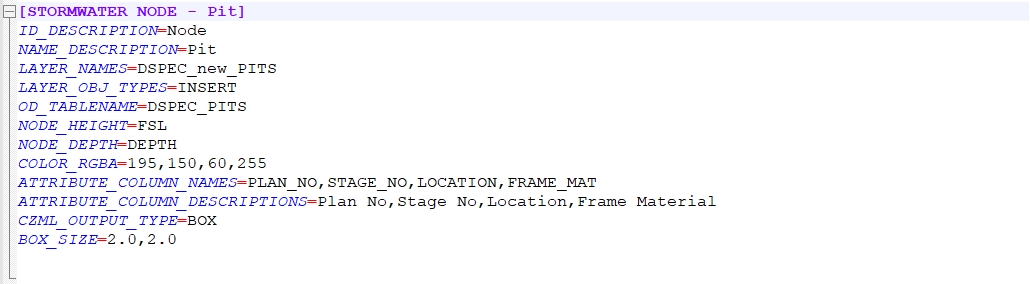
Fig: Example of Export Definition file for Stormwater Pit Node.
Or a Sanitary Sewer node such as an Access Point can be denoted as a circular object type, such as a TUBE using the following parameters:
- CZML_OUTPUT_TYPE: The Object type used to represent the spatial object. Sanitary Sewer Access Points can be defined as a TUBE.
- TUBE_RADIUS: The radius assigned to the Tube type i.e. 1.5.
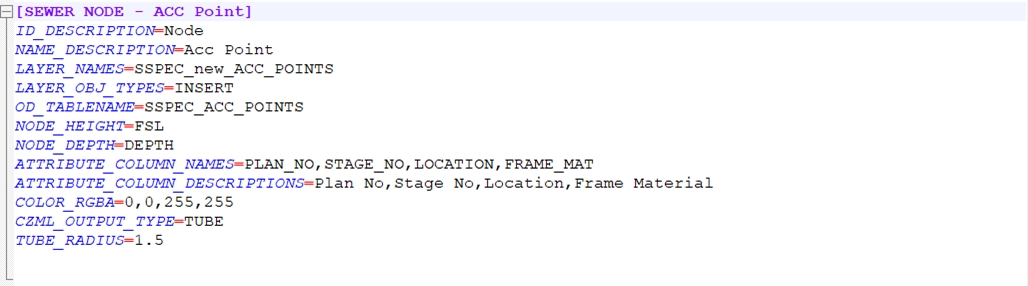
Fig: Example of Export Definition file for Sanitary Sewer Access Point Node.
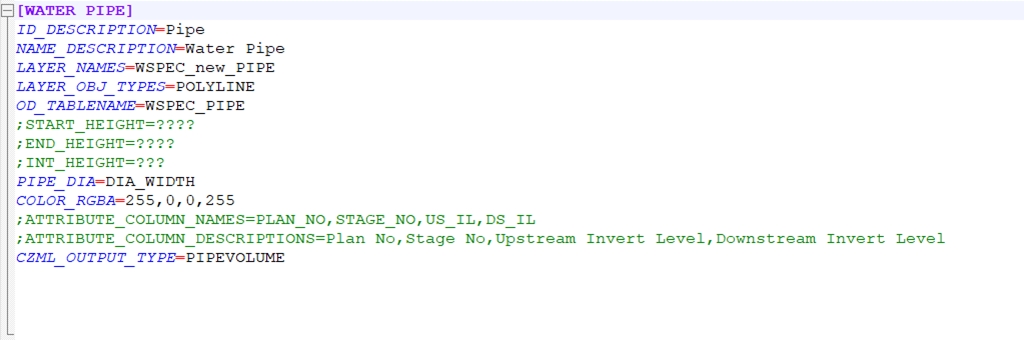
Fig: Example of Export Definition file with parameters commented out.
Exporting Drainage Nodes and Pipes to CZML file Format
Before any drainage objects can be exported to CZML format they must have passed the validation process. When the data is exported to CZML format, the geometry for each object is transformed to WGS84 (X;Y;Z values).
To export the drainage pipes and/or nodes, do the following:
- Ensure the drainage objects in the AutoCAD drawing have passed validation without any errors.
- Copy the default CZMLDef.ini file and save as another filename, ensuring the original file does not change.
- Edit the CZMLDef.ini to incorporate all the necessary configurations required.
- Select the Export Objects to CZML icon
 on the ACDC toolbar or select the Export Objects to CZML option from the ACDC Menu.
 - The CZML ini File dialog box is displayed and defaults to the C:\Program Files\Open Spatial\ACDC 6.0 folder where the configuration file was installed.
- Select the edited configuration file from the list displayed in the CZML ini File dialog box.
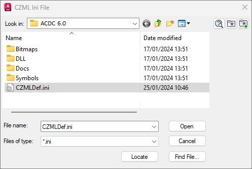
Fig: CZML ini File dialog box - Select the configuration file to apply to the export, and then select OPEN.
- The Save CZML as dialog box is displayed and defaults to the folder location where the drawing was opened, and the file name defaults to the same as the drawing file.
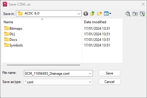
Fig: CZML ini File dialog box - On this dialog box, specify the name and folder where the resultant .czml file will be saved to.
- At the command line you are prompted to select the sewer or drainage objects to export, and then press ENTER. The command line indicates the number of objects selected, as well as the date and time stamp of when the export started and ended.
- If there are no errors during the export process, the resultant .czml file is created.
- The following extract is an example of an exported drainage pipe:
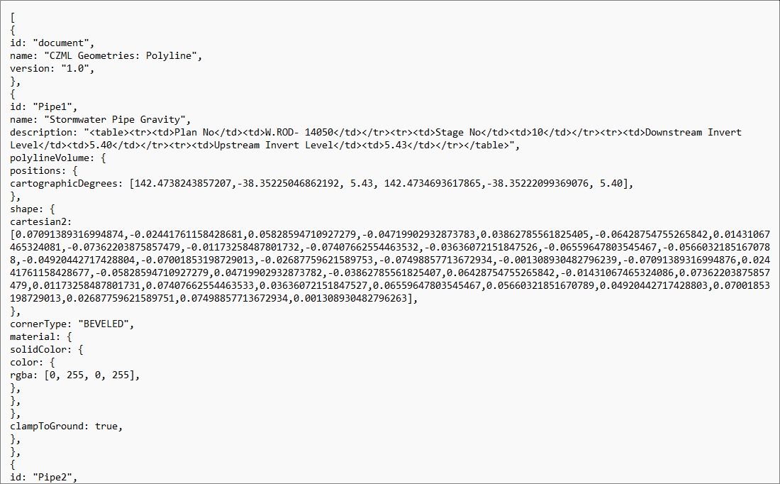
Fig: Example of CZML output for a Drainage Pipe - The following extract is an example of an exported drainage node:
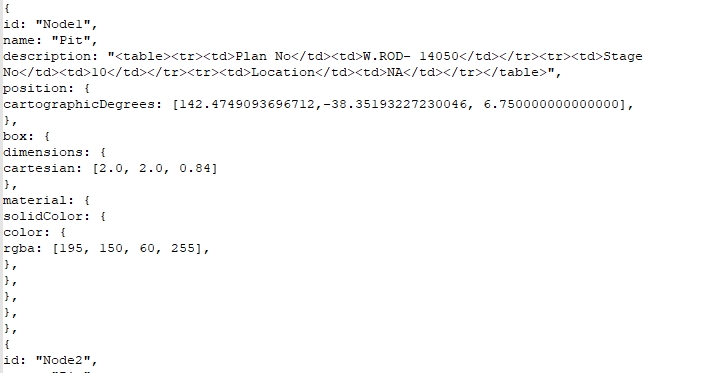
Fig: Example of CZML output for a Drainage Node