Validation Process
The Validation process compares the data in the open drawing file against the stored configuration and validation rules in the database. These rules are constructed during the configuration process. Data in the drawing that violates the defined rules will be flagged as errors and must be addressed before the data can be converted. Once all errors are addressed, the Validator will construct all the required attribute information into the format defined in your configuration. The attribute information for each asset in the open drawing will be stored in object data tables created on each applicable object in the drawing.
If a drawing has already been validated, the system will display the following message on the command line: Drawing already validated - exiting routine. The routine automatically exits and does not delete the Object Data tables.
If the user clicks on cancel, while it is still processing objects then orphan records will also be removed from the WAE_ERRORS_OBJ database table.
If the drawing has not yet been validated then the system will proceed with validation and delete the object data tables. When this happens, drawings which has previously been validated may have changed geometry objects such as splitting of linear objects.
Run the Validate ACDC Drawing Tool
To complete the validation process, follow the steps below.
- Open ACDC application by selecting the ACDC icon on the desktop.

- Open the AutoCAD drawing file to be validated by typing the AutoCAD command Open at the command line, and navigate to the required drawing.
- On the ACDC Toolbar press the Connect to Database button
 and connect to the required configured database which contain the ACDC system tables.
 - On the ACDC Toolbar press the Validate ACDC Drawing button
 .
. - When prompted to overwrite the validation report file, select the appropriate option (Y will overwrite all data in the report file, while N will add the new information to the end of the file). You can inspect this file for a list of all the validation errors.
- When prompted to select the objects based on Current or All configured layers, if the selection parameter is set to All then all configured layers present in the drawing will be turned on (thawed). If the selection is set to Current then layers which are not configured will be turned off/frozen.
- Select the objects you wish to validate against your stored configuration. You can do this by either manually selecting the objects in your drawing using the mouse, or you can simply type All to select all the objects within the drawing file. It is recommended that you always run the Validator on ALL objects in your drawing.
- Press the Enter key on your keyboard, or press the right-button on your mouse to begin the validation routine.
- The command line provides feedback for the number of entities being processed based on the number of objects selected.

Fig: Validation Process Progress on Command Line. - Upon completion, the results of the validation routine will be displayed on the command line. Select F2 button to display an expanded view of the Command Line to be able to view all the results.
Error Message Handling
If errors were detected during the Validation Process, the error messages are written to the log file, using similar syntax as illustrated below:
[Number of objects] [Entity Type(s)] on layer [Entity Layer] skipped. Entity Type not valid in configuration
An error message will also be printed on the command line and error circles will be placed in the open drawing file.
If any errors are picked up during the validation process then the Enhanced Attribute Editor dialog will be displayed. In this the error blocks will be displayed with the entity name (blockname) or object type and layer name. This will avoid any confusion the user may have as to which error pertains to which block or object type on which layer.
When validating a geometry type, if the drawn geometry type does not match the configured geometry types for line, point and polygon objects, the system will display an error in the validation results in the following syntax e.g. Incorrect Object Type (SPLINE). - [Layer: OSPEC_NEW_AREA_EXTENT].
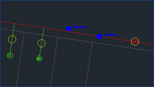
Fig: Objects with Attribute Errors Flagged with Yellow Circles.
As part of the Configurator Settings, the default color of the Error and Warning circles can be set for Attribute Errors/Warnings, Geometry Errors/Warnings, Break Errors/Warnings and Database Extents Errors/Warnings.
- gAttributeErrorColour: Default color set to Yellow.
- gAttributeWarningColour: Default color set to Yellow.
- gCannotBreakErrorColour: Default color set to Cyan.
- gCannotBreakWarningColour: Default color set to Cyan.
- gExtentsErrorColour: Default color set to Magenta.
- gExtentsWarningColour: Default color set to Magenta.
- gGeometryErrorColour: Default color set to Red.
- gGeometryWarningColour: Default color set to Red.
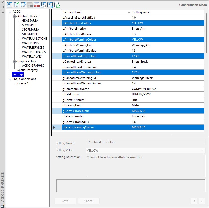
Fig: Configurator Error and Warning Circle default settings.
Below is a screen shot of a flagged geometry error (red circle). In this case the error is that the closed polyline object contains two attributed blocks.
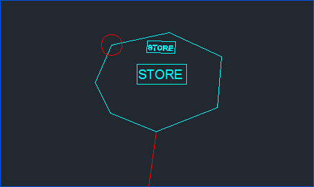
Fig: Red Circle Flagged Geometry Error.
A report file (.log file) is also created by the ‘Validate ACDC Drawing’ tool. The report file is given the name specified by the gReportFile setting and is placed in the directory specified by the gReportFileLocation setting. By default, the report file name and location are set to be the same as the currently open drawing file. The report file contains a log of all the errors found during validation. For each error the report file will contain its coordinates, the created error block name, and the associated error message.
- To view the details of an error, simply select an error circle (Red for geometry errors and yellow for attribute errors) and view the error circle properties. The error information is contained in the ‘Block’ section of the properties dialog. As per the example below, one object or block may have more than one error listed in the properties pane.

Fig: Error Properties - Address each error and fix accordingly.
- Once you have addressed each flagged error, run the Validator once again on all of the data in the drawing. If all errors have been fixed successfully, you should see zero counts against the different error types in the command line and should check the number of objects selected vs the number of objects passed.
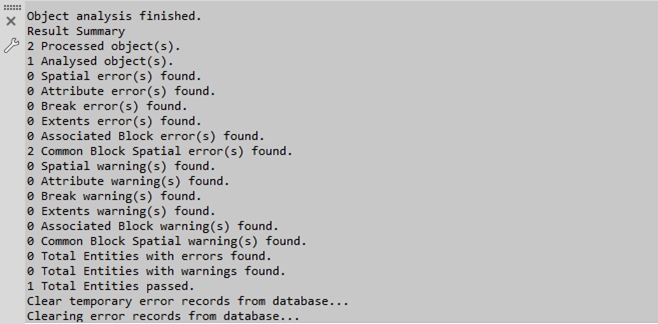
Fig: Successful Validation RunThe above command line feedback indicates a successful validation run. On a successful validation run, the data within your initial selection passes all validation checks. As such, these objects are recorded as validated and will not be re-inspected by the Validator on subsequent validation runs.
Errors which are picked up during validation are stored within WAE_ERRORS_OBJ database table. When an error is flagged, it will be displayed in the below syntax, where the xxx variables indicate the Layer Name and the yyy variables the Block Name respectively. This will be displayed in both the WAE_ERRORS_OBJ database table and the resultant Log file.
Error Message - [Layer: xxx - Block: yyy]
for example:
WAE_ERR_190,Error: Invalid substring (RD) compare for tag (MATERIAL) - [Layer: ACDC_STORMPIPES - Block: STORMPIPES]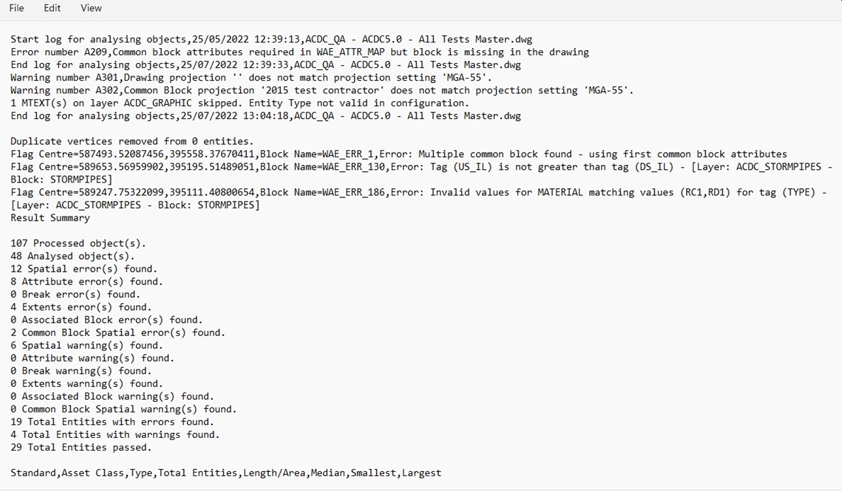
Fig: Errors written to Log fileThe log file also contains a detailed report on all Asset classes that are in the project and are listed according to the Layer and Geometry type with the following extended information:
- Class.
- Type.
- Total Entities.
- Length / Area.
- Median.
- Smallest.
- Largest.
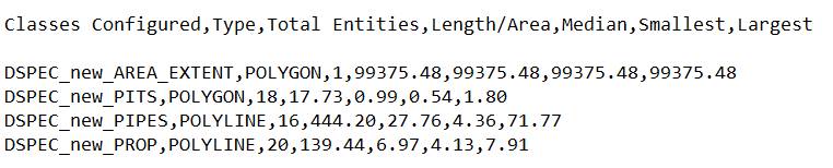
Fig: Detailed Asset Classes reportOnce a validation has been run, the table WAE_ERRORS_OBJ is automatically truncated to prevent historic errors from being flagged. Validated objects will have their final attribute information recorded in object data tables. To view this information, select a validated object in your drawing and view its properties. You will see that an OD section has been added to the feature that contains all applicable attribute information:
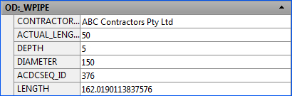
Fig: Validated Object AttributesThis information is what will be transferred across to your destination tables in the conversion process.
In the properties dialog of a validated object you will also see a section titled OD: ACDC_VALIDATED. This indicates that the object has been validated.

Fig: Validation ConfirmationIn a successful validation run, snapping and breaking rules will be carried out on all the selected objects.
- OSX_AP_SETTINGS: Stores the settings information used during the Validation and Conversion processes.
- WAE_OBJECT: Defines the objects to be Validated/Converted, their geometry types, associated blocks, and destination layers.
- WAE_ATTR_MAP: Stores the definition of attributes to be stored for each defined object type.
- WAE_PIPE_BREAK: Lists the details of defined snapping rules.
- WAE_SC_LINK: Defines the layers that contain objects to which service connection can connect.

Fig: Configurations loaded at the start of Object ValidationThe user is then prompted to overwrite the report log file or not. By default No will append the entries from the validation process to the existing log file. If the user selects Yes to overwrite, the log file is re-created during the validation process.

Fig: Overwrite log fileWhen the user is running a validation on the selected objects, the system will display a prompt: Select objects based on current or all configured layers? [Current All] :
- The Current option will turn off all layers and only displays those layers that have been configured as part of the Configurator.
- The All is selected then the routine will not change any layers (turning them on or off) when the user is prompted to select objects to validate.

Fig: Later selection for Validation
Validation Errors
The validation errors can be categorized into the following Error types:
- Common Extents Error
- Common Projection Error
- Common Spatial Errors
- Common Attribute Errors
- Common Break Errors
- Common Block Errors
- Common Complex Validation Errors
Common Extents Error
The following table describes the common Extents Error message logged in the Validation Log, the causer, and how to remedy so that it passes validation once corrected and re-submitted.
| COMMON EXTENTS ERROR | ||
| Error Description | Error Cause | Error Fix |
|
Error: Entity found outside of configured ACDC extents
|
An entity captured in the drawing falls outside the database extents defined for the project. The maximum and minimum X;Y extents are configure per asset owner, and in some cases per project. Image shows the coordinates of the selected attribute block falls outside of the configured extents. |
Check the coordinate system saved with the drawing and ensure it is set to the correct coordinate system for the asset owner. Use the AutoCAD command ADESETCRDSYS to assign the correct coordinate code from the Coordinate System Library.
Image shows Coordinate System Code and X;Y coordinates of the selected attribute block. |
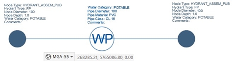
Table: Extents Error description, the error cause and remedy to fix.
Common Spatial Errors
The following table describes common Spatial Errors messages logged in the Validation Log, what potentially caused the error, and how to remedy the error so that it passes validation once corrected and re-submitted.
| COMMON SPATIAL ERRORS | ||
| Error Description | Error Cause | Error Fix |
| Error: More than one object found with associated block - [Layer Name] |
Error caused by the duplication of an object with the same attribute block where the objects have been captured on top of each other. The Layer Name in the error description will advise on which layer tin the Layer Name. |
Ensure there is only one object by using AutoCAD's LIST command and selecting the objects using crossing window or crossing polygon. Delete the duplicate object.
Image shows where there is only one Polyline in the selection set.
|
| Error: Associated block on incorrect layer - [Layer Name - Block Name] | Error caused when the block has been captured on the incorrect layer in the drawing according to the block type. The layer for the associated block does not match any of the associated block layers for the block in the configuration. The error description will advise on which layer the error occurs as well as the block name. 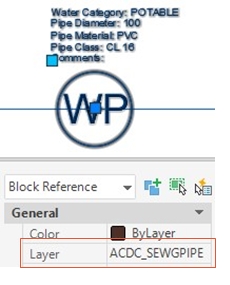 Image shows a water attribute block incorrectly captured on the Sewer Gravity Pipe layer. |
Ensure the block has been captured on the correct layer according to the block type by checking the following:
Image shows water attribute correctly captured on the Water Pipe layer. |
| Error: [count] attribute blocks found (where [count] denotes the number of blocks found) |
Error caused when more than one attribute block has been captured and snapped to a single object such as a water pipe, or within tolerance of the same entity.
Image shows two pipe attribute blocks captured for the same pipe object. |
Ensure there is only one attribute block captured and snapped to a polyline or polygon object.
Image shows only one attribute block snapped to a single pipe object. |
|
Error: [count] attribute blocks found at end of this SC or Error: [count] attribute blocks found at start of this SC |
The error is caused by the incorrect pipe direction of the service connection in relationship to the connecting pipe.
|
Correct the direction of the service connection.
|
| Error: Isolated configured block found |
The attribute block is not snapped correctly to the pipe or service connection. This will be accompanied with a No attribute block found attribute error for the pipe or service connection.
For POLYGON and CIRCLE objects the error might be caused when the attribute block is not found within AutoCAD object. |
Ensure the attribute block is correctly snapped to the object, for example the attribute block insertion point must be snapped onto the endpoint of the water service connection.
In the case of a polgon object, this error can often be accompanied by Error: Configuration indicates LWPolylines on this layer should be closed. This would indicate that because the polyline was not closed that the validation didn’t associate the block to the polygon, for this closing the polyline will resolve both errors.
|
The attribute block has been snapped to an incorrect object which it isn’t associated with. For example, a pipe has been incorrectly drawn using a service connection Polyline and the attribute block has been placed on this line.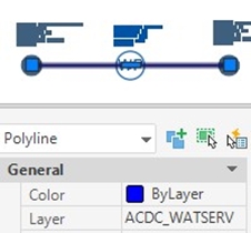 This image shows a water pipe that has been drawn incorrectly on the water service connection layer ACDC_WATSERV. |
Ensure the pipe/service connection is captured on the correct layer according to the object type.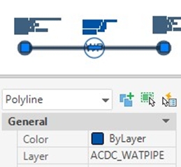 This image shows the water pipe has been drawn correctly drawn on the water pipe layer ACDC_WATPIPE. |
|
|
Error: No attribute block found. - [Layer: Layer Name]
|
A pipe has been drawn as an Arc or Line, not as a Polyline. ACDC is only compatible with Polylines and will not recognize Arcs or Lines as objects.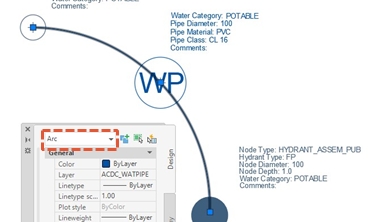 This image shows a curved pipe which has been incorrectly drawn as an arc. The square grip as a midpoint indicates that the curve has been drawn as an arc. |
Ensure all pipes and service connections are drawn using Polyline or the tools provided by the asset owner.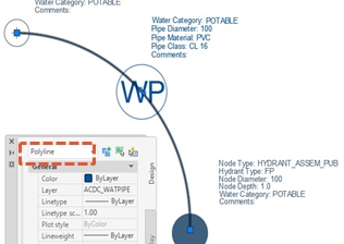 The image shows a curved pipe which has been correctly drawn as a Polyline (as opposed to an Arc). |
An erroneous attribute block was placed in the drawing by mistake.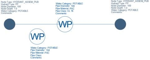
|
Delete the offending attribute block.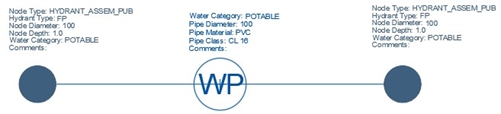 |
|
The attribute block is not snapped correctly to the pipe, this will be accompanied with an Isolated configured block found error for the attribute block.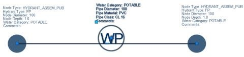 This image shows an attribute block which isn’t snapped correctly. |
Ensure the attribute block is snapped to the centre point of a pipe.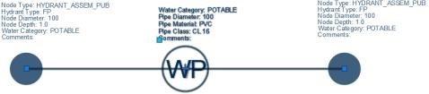 This image shows a correctly snapped block. |
|
The attribute block for a water pipe is missing where the error message would read Error: No attribute block found. [Layer: ACDC_WATPIPE].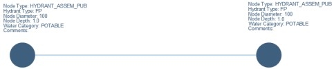 This image shows a pipe without an attribute block. |
Place the attribute block and complete the required and known attribute fields accordingly.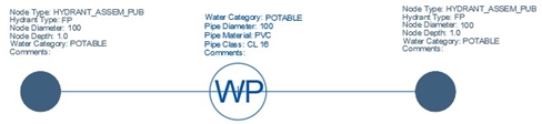 This image shows a pipe with an attribute block. |
|
The attribute block hasn’t been snapped to the midpoint of the pipe, but at the endpoint of the Water pipe.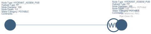 This image shows an attribute block incorrectly snapped to an end point of a Polyline. |
Place the attribute block at the correct position on the Water Pipe and fill in the attribute fields accordingly.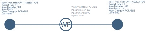 This image shows an attribute block correctly snapped to a midpoint of a Polyline. |
|
| Error: No valid object layer/type combination found | The main pipe which the service connection connects to has been drawn as an incorrect object (e.g. a service connection object has been drawn instead of a pipe object).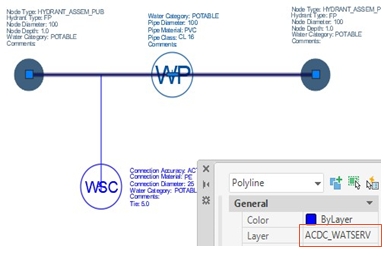 This image shows a water pipe drawn as a service connection. |
Ensure all pipes have been created as correct pipe objects.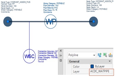 This image shows the water pipe drawn as the correct type. |
| Error: Incorrect Object Type [ObjectType] on layer [Layer Name] | This typically occurs if something has been drawn on an incorrect layer which doesn’t contain that object type. (e.g. a water node being placed on the sewer pipe layer). The error message details the Object Type and the layer on which it has been incorrectly captured. 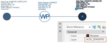 This image shows a water node on the gravity sewer pipe layer. |
Ensure all objects are drawn on the right layer or use the tools provided by the asset owner. Move the object onto the correct layer configured for the object type, or delete the entity if it should not be in the drawing. 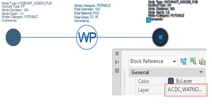 This image shows a water node on the water node layer. |
| Error: Point within snap tolerance | This can be caused by pipe Polylines which has been overlapped with one node snapped between them. 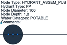 This image shows two pipes overlapping, where the node is in-between the overlap. |
If distance to snap the point is less than the LinearChkTol setting and greater than LinearSnapTol setting, then an error is flagged. Ensure that pipes are correctly snapped to start and endpoints and the node is correct snapped. 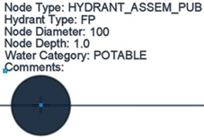 This image shows a node snapped correctly to two pipes. |
|
This error can also occur when two lines are close but are not snapped to the same endpoint.
This image shows two lines which have not been snapped to the same endpoint. |
If the lines are less than 0.02 apart the lines will be automatically snapped together and will pass validation.
|
|
| Error: Associated block is contained within more than one configured object |
The attribute block falls inside more than one configured polygon or circle object such as a Road Reserve. There may only be one attribute block associated falling inside the road reserve polygon. |
Delete the duplicate Road Reserve so that the tag is only associated to one configured polygon.
|
| Error: Associated block is not contained within configured object |
The attribute block falls outside as "Inside" Polygon/Circle object and is found not within a configured object then it will be flagged as error. The attribute block must be located inside the associated Road Reserve polygon. |
Move the attribute block to inside the associated configured polygon.
Potential issue: When a closed polyline exists within another closed polyline the system cannot differentiate and may give an error. Please note nested assets cannot currently be submitted in one drawing and must be submitted on separate drawings. Alternatively use MPolygons in Map3D |
| Error: Configuration indicates LWPolylines on this layer should be closed. | According to the configuration, the system expects closed polylines or polygon objects, however open polylines exist on the layer. | Ensure all LWPolylines on the configured layer are closed. |
| Error: Entity area [area] is less than minimum tolerance [tolerance] allowed | The calculated area of the entity is less than what is permitted in the configuration setting gPolyMinArea. | Either correct the entity to have an area larger than what is configured, or increase the configured setting gPolyMinArea which has a default value of 0.25. |
| Error: Entity length [Length] is less than minimum tolerance [Tolerance] allowed | The length of the line/polyline entity is less than what is permitted. This is configured using the setting gLinearShortTol. | Make sure that the line/polyline captured is longer than the configured shortest length configured, or update the setting gLinearShortTol to be larger than the default value of 0.5. |
|
Error: No attribute block found - [Layer Name] at start of this SC
or
|
The validation checks cannot not find an attribute block at the end/start of the water/sewer service connection.
|
Check if an Attribute block has been captured for the start/end of the Service Connection. It may require the direction of the Service Connection to be changed. Check that the Attribute block is captured and snapped to the end of a Water Service Connection. Check that the Attribute block is captured and snapped to the start of the Sewer Service Connection.
This image shows the attribute block has been snapped to the end of the Water Service Connection. |
The service connection has been drawn in the wrong direction. Water service connections must be drawn from the pipe into the lot. Sewer service connections must be drawn going out of the lot into the pipe.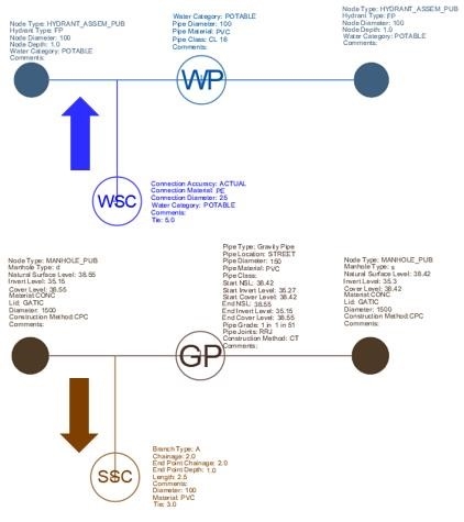 This image shows incorrect direction drawn for service connections. |
Consider the flow of the assets. Water to the lot, Sewer from the lot. Ensure service connections have been drawn in the correct direction. Use the REVERSE command to change the direction.
This image shows the correct direction of flow the service connections are to be drawn in. |
|
| Error: No main pipe found at start of this SC or Error: No main pipe found at end of this SC |
The service connection is drawn but does not snap correctly to the main pipe.
|
Ensure service connections are snapped to the main pipe correctly. This can be achieved by using the Nearest object snapping mode.
This image shows a service connection correctly snapped to a pipe. |
The attribute block has been incorrectly drawn on the pipe side of the service connection.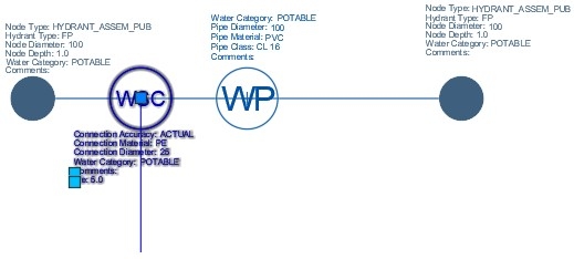 This image shows a service connection attribute block on the wrong endpoint of the service connection. |
Ensure that the attribute block is on the lot/parcel side of the service connection.
This image shows a service connection block on the correct endpoint side. |
|
The service connections are tied to a previous stage, and the existing pipe has not been drawn.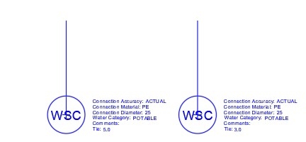 This image shows service connections that are not connected to any pipe. |
Ensure the service connections are snapped to a pipe on the Existing Pipe layer (ACDC_EXPIPE). Do not draw a pipe using the Water Pipes layer.
This image shows service connections that are connected to a pipe on the Existing Pipe layer. |
|
The main pipe which the service connection joins to has been drawn as an Arc or Line, not a Polyline. ACDC only supports Polylines.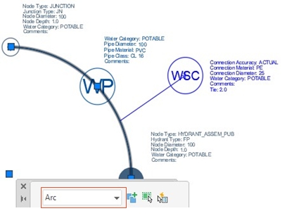 This image shows a pipe drawn as an Arc. |
Ensure all pipes are drawn using Polylines or the tools provided by the asset owner.
This image shows a pipe drawn as a Polyline. |
|
| The service connections are tied to a previous stage, and the existing pipe has not been drawn. This image shows service connections that are not connected to any pipe. . |
Ensure the service connections are snapped to a pipe on the Existing Pipe layer (ACDC_EXPIPE). Do not draw a pipe using the Water Pipes layer.
This image shows service connections that are connected to a pipe on the Existing Pipe layer. |
|
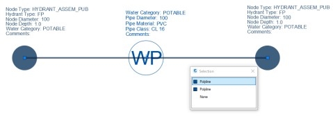
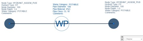
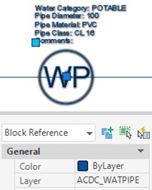
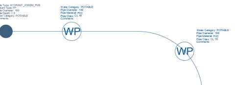
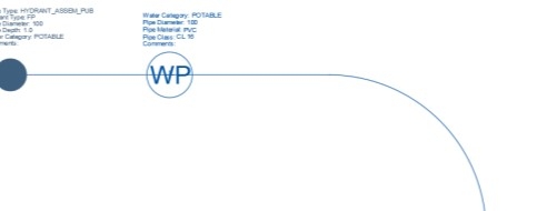
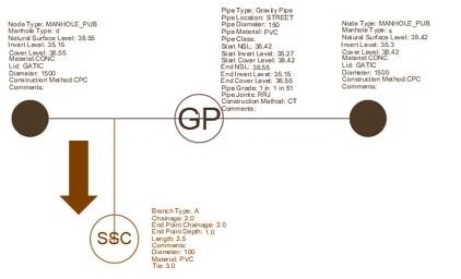
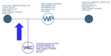
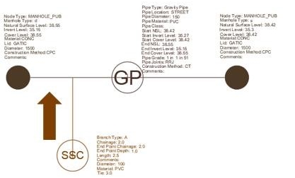
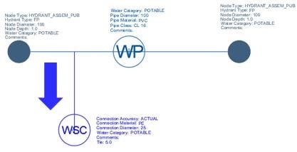
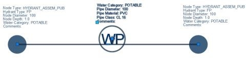
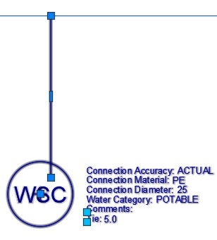
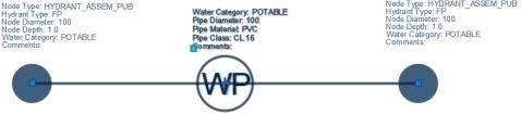
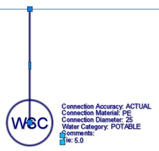

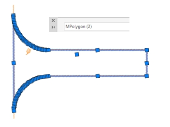
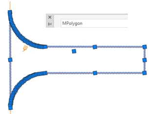
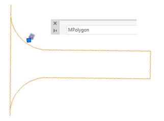
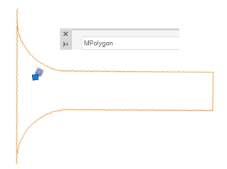
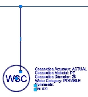
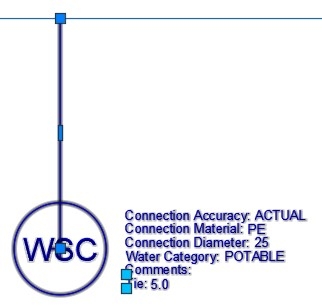
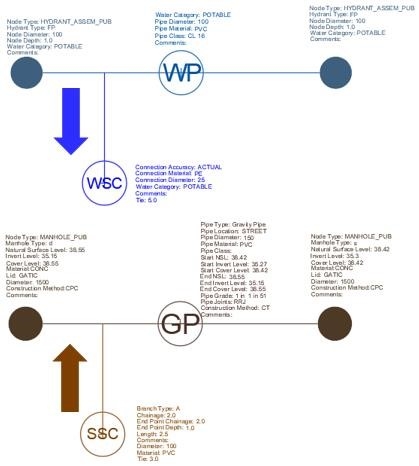
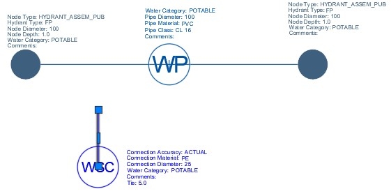
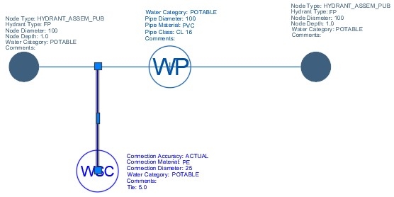
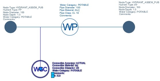
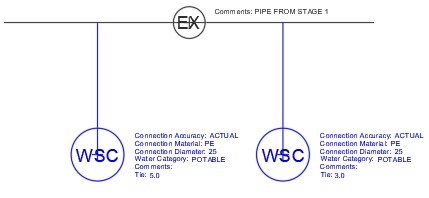
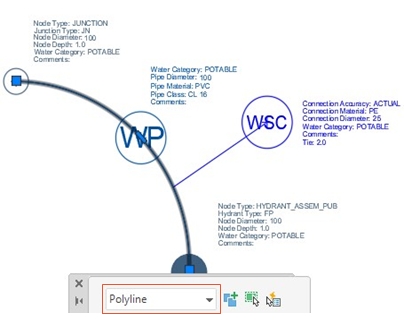
Table: List of common Spatial Error descriptions, the error cause and remedy to fix.
Common Attribute Errors
The following table describes common Attribute Errors messages logged in the Validation Log, what potentially caused the error, and how to remedy the error so that it passes validation once corrected and re-submitted.
| COMMON ATTRIBUTE ERRORS | ||
| Error Description | Error Cause | Error Fix |
| Error: Cannot retrieve tag [Tag_Name] | This error indicates that the validation could not retrieve the tag for the provided TAG_NAME for the associated attribute block. This can also be caused by corruption of the block definitions within the provided drawing, or it is an administration type issue. |
Check that configuration is referencing the correct tag in block. Check the tag exists in block definition and that the TAG_NAME matches the configuration. In the event of a corrupt blocks within the drawing, purge the drawing of all unused Blocks, Groups etc. This can be accomplished by using the AutoCAD PURGE command, and selecting All Items.
If validation continues to fail, contact the asset owner or the Open Spatial Support Team for assistance. |
| Error: Date value is in an invalid format for tag [TagName] - [Layer Name - Block Name] | This is caused by the date being captured in the wrong date format in the specified attribute block, or even the common block attributes. The date must match what is configured for the gDateFormat setting.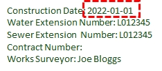 This image shows the date in an incorrect format. |
Ensure the date matches the configured format for the gDateFormat setting i.e. DD/MM/YYYY as the international date format or MM/DD/YYYY as the USA date format.
This image shows the date in the correct format. |
| Error: Invalid numerical value for tag [TagName] - [Layer Name - Block Name] | This error is caused when a non-numerical character is captured for a field in an attribute block which is configured for numerical values only.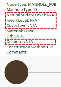 This image shows a non-numerical character in a numerical field.. |
Ensure there is only numerical values in the field flagged in the error.
This image shows numerical values in numerical fields. |
| Error: Missing mandatory value for tag [TagName] - [Layer Name- Block Name] | This is caused by a mandatory attribute field mistakenly not being captured.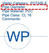 This image shows a mandatory field not captured. |
Fill in the field that has been listed in the error message.
This image shows the mandatory field captured. |
| In the event mandatory attributes have been specified for a specific object, if the mandatory value is missing the object will be flagged as an error indicating the layer on which the attribute block is found, the name of the attribute block and the tag name where the mandatory attribute is missing. In the example below, the Sewer service connection with a Branch Type OB or B must have a value in the Length field of 0.0 if the length is not known. It may not be left blank. 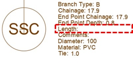 This image shows a sewer service connection block of Branch Type B with no Length value. |
Provide value for the relevant tag/attribute.
This image shows the service connection block of Branch Type B with a Length value of 0.0 |
|
| Error: Numerical value too large for tag [TagName] - [Layer Name - Block Name] | This is usually caused by a typing mistake in one of the numerical fields where the tag value entered falls outside the maximum range permitted.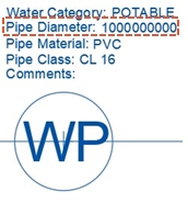 Ensure values within the flagged field are correct and adhere to Appendix 1 of the ACDC As Constructed Submission Requirements. |
Ensure values within the flagged field are correct and adhere to Appendix 1 of the ACDC As Constructed Submission Requirements.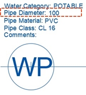 This image shows the pipe Diameter within the correct numerical range. If the value entered is correct and the error persists, contact the asset owner for assistance. |
| Error: String too long for tag [TagName] - [Layer Name - Block Name] | This is usually caused by the tag value exceeding the character limit configured for the tag name in the attribute block.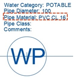 This image shows the pipe Material as an incorrect value. |
Review the specified tag value on the attribute block and shorten to match length specified by the customer’s standard. Ensure the values within the flagged field are correct and adhere to the specification requirements.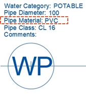 This image shows the pipe Material with a correct value. If the value entered is correct and the error persists, contact the asset owner for assistance. |
| Error: Value is not an integer for tag [TagName] - [Layer Name - Block Name] | For the specified tag name, the data entered is not a whole number. This is usually caused by a typo in one of the fields. Either a decimal value has been added or a non-numerical character has been added i.e. 100mm 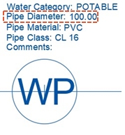 This image shows the pipe Diameter value to two decimal places. |
Review the specified tag on the block highlighted and update it to a whole number. Ensure the values within the flagged field are correct and adhere to the ACDC As Constructed Submission Requirements. 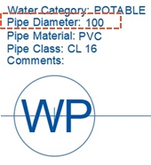 This image shows the pipe Diameter with a correct value. If the value entered is correct and the error persists, contact the asset owner for assistance. |
| Error: Cannot retrieve function for [TagName] | Could not find the Function in the database for the specified Tag Name. |
Check database logon user has necessary access/privileges to Function and that the Function exists in database. Check that the Function name in the configuration is correct. If configuration is correct, then contact your asset owner or Open Spatial. |
| Error: Cannot retrieve procedure for [TagName] | Could not find the Procedure in the database for the specified Procedure. |
Check database logon user has necessary access/privileges to Procedure and that the Procedure exists in database. Check that the Procedure name in the configuration is correct. If configuration is correct, then contact your asset owner or Open Spatial. |
| Error: Cannot retrieve sequence for [TagName] | Could not get next sequence number from database for the specified Tag Name. |
Check database logon user has necessary access/privileges to Procedure and that the Procedure exists in database. Check that the Procedure name in the configuration is correct. If configuration is correct, then contact your asset owner or Open Spatial. |
| Error: Invalid LCODE for tag [TagName] - [Layer Name - Block Name] | A value in the Attribute Properties has been captured but does not exist in the configured lookup table. | Either add the missing attribute value to the lookup table, or correct the attribute to match one of the attribute values configured in the lookup table. |
| Error: Invalid string value for tag [TagName] - [Layer Name- Block Name] | If any character in the block attribute tag value is not a valid ascii character value i.e. ASCII Code < 32 or ASCII Code > 126 |
Make sure only permitted characters are used for the specified tag/attribute |
| Error: Invalid values for [Tag] matching values [Tag Values] for tag [TagName] - [Layer Name- Block Name] |
An invalid value has been captured for the attribute tag in a scenario where if a value in Attribute X = [value] then the value in Attribute Y can only be one of the following [list].
For example, if the Pipe Material = RC2 then the corresponding Pipe Diameter can only be one of the following permitted values 50, 65, 80, 100, 125, 150. |
Change the offending pipe diameter value to one that is configured in the table WAE_ATTR_MVRULECHECK, or add the missing pipe diameter value to the table if it is valid. |
| Error: Numerical value too small for tag [TagName] - [Layer Name - Block Name] | Attribute tag value falls outside of Range Minimum i.e. < Range Min. | Ensure the tag value falls within the range configured for the specified block. |
| Error: Primary Object [Block Name/TagName] Value is not less than or equal to adjacent object [LayerName/TagName] |
Combined Spatial and Attribute Checks where:
|
In the case of the Sewer Gravity Pipe example provided, the Upstream Pipe Diameter must not be bigger than the Downstream Pipe Diameter, based on the drainage reticulation being a gravity network.
Error: Primary Object (SSPEC_PIPES/DIA_WIDTH) Value is not less than or equal to adjacent object (SSPEC_PIPES/DIA_WIDTH).
Ensure that the Pipe Diameters for both the Upstream and Downstream pipes has been captured correctly.
|
| Error: Missing mandatory value for tag [XYZ_FIELD] | This is caused by a mandatory field that has not been captured. This image shows a mandatory field not captured. |
Capture the mandatory tag value for the field recorded in the error message.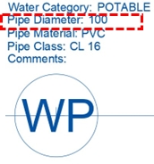 This image shows the mandatory field captured. |
| Sewer service connections where the Length value is not captured. If you do not know the length then capture a value of 0.0 but do not leave as blank. This image shows a sewer service connection block with no Length value. |
Draw the service connection with a length of 1.0m, but enter the Length value as 0.0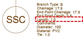 This image shows the service connection block with a Length value of 0.0 if unknown. |
|
| Numerical value too large for tag [XYZ_FIELD] | This is usually caused by a type in one of the numerical fields. This image shows the Pipe Diameter value as being too large. |
Ensure values within the flagged field are correct and adhere to Appendix 1 of the ACDC As Constructed Submission Requirements. This image shows the Pipe Diameter captured within the correct numerical pipe diameter range. |
| String too long for tag [XYZ_FIELD] | This is where the text value exceeds the permissible text length configured for the tag. This image shows the pipe Material as an incorrect value where the pipe material contains the material and class values. |
Ensure the text value for the tag conforms to the length configured. This image shows the Pipe Material captured with a correct value, and the Pipe class captured as a separate tag value. |
| Value is not an integer for tag [XYZ_FIELD] | This is typically caused by a typo in one of the fields. Either a decimal value has been added to a field which is a non-integer value, or a non-numerical character has been added. This image shows the pipe diameter value with decimal places. |
Ensure values within the flagged field are correct and adhere to the ACDC As Constructed Submission Requirements. This image shows the pipe diameter with a correct value. |
.jpg)
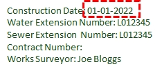
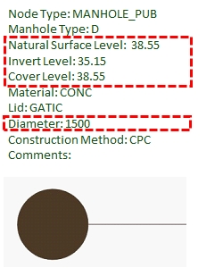
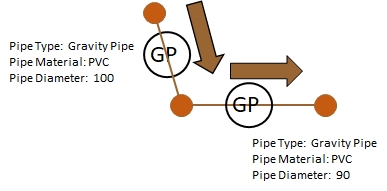
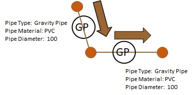
Table: List of common Attribute Error descriptions, the error cause and remedy to fix.
Common Break Errors
The following table describes common Break Errors messages logged in the Validation Log, what potentially caused the error, and how to remedy the error so that it passes validation once corrected and re-submitted.
| COMMON BREAK ERRORS | ||
| Error Description | Error Cause | Error Fix |
| Error: Cannot break pipe as new segments too short | Breaking Pipe might cause either 1 or both new pipe segments to be too short according to configuration setting PipeLengthBreakTol. The minimum permissible length of pipe to be created by a break operation is 0.5. This can also be caused by a snapping error where the pipes do not snap to the insertion point of the node. 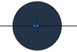 This image shows a node incorrectly snapped to pipes, within the breakage tolerance (0.9m). |
Update PipeLengthBreakTol setting or update drawing object and increase length of pipe to be greater than 0.5 when it is broken. This setting is configured to be 0.5 by default. Ensure that nodes are snapped correctly to the endpoints of the pipes and ensure the pipe length is greater than 0.9m. |
| Error: Cannot snap block. Ambiguous destination points |
When snapping node to pipe Snap nearest end/point and there is more than 1 snap point detected. The distance from the block insertion point to the snap point gNodeSnapTol setting and the distance is greater than 0.0001. This can be caused by an accidental duplication of pipe Polylines (e.g. Two Polylines that sit on top of each other. |
Check the pipe to which the node is being snapped to and ensure there are not two or more break points within the distance configured. This setting is configured to be 0.1 by default. Ensure there is only one Polyline per pipe and delete any duplicates. |
| Error: Cannot break. Ambiguous destination points |
This error occurs when snapping a node to a pipe and breaking the pipe Snap nearest point and break and there is more than 1 break point detected The distance from the block insertion point to the snap point is smaller than the gNodeSnapTol setting. |
Check the pipe to which the node is being snapped to and ensure there are not two or more break points within the distance configured. The gNodeSnapTol setting is configured to be 0.1 by default.
|
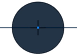
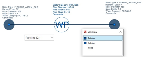
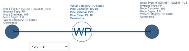
Table: List of common Break Error descriptions, the error cause and remedy to fix.
Common Block Errors
The following table describes common Common Block Errors messages logged in the Validation Log, what potentially caused the error, and how to remedy the error so that it passes validation once corrected and re-submitted.
| Error: Multiple common block found - using first common block attributes | This error is caused by there being more than one Common Block captured in the drawing. | Only one Common Block is permitted per drawing, so delete the duplicate Common Block. |
| Error: The common block "COMMON_BLOCK" could not be found in the drawing. The process cannot continue. | The Common Block is a mandatory Attribute Block that must be present in each Drawing. If the Common Block is not present or has a different name to what is configured, an error message is logged indicating this Common Block cannot be found, and the process cannot continue. The name of the common block must match the gCommonBlkName setting defined in the Configurator settings. |
Ensure that the Common Block attribute block is present in the drawing, has the same name as what is configured and falls within the database extents. |
Table: List of Common Block Error descriptions, the error cause and remedy to fix.
Validation Warnings
During the validation process warning messages may be logged for various discrepancies detected, but do not fail the submission. The table blow describes common Validation Warning messages logged in the Validation Log, what caused the warning, and how to remedy the warning if deemed necessary
These validation errors can be categorized into the following Error types:
- Validation Warnings
- Complex Validation Warnings
Common Validation Warnings
The following table describes common Validation Warnings messages logged in the Validation Log, what potentially caused the warning, and how to remedy the warning. Warnings do not prevent the submission from passing Validation.
| COMMON VALIDATION WARNINGS | ||
| Error Description | Error Cause | Error Fix |
| Warning: Common Block could not be found in the drawing | The Common Block is a mandatory Attribute Block that must be captured per Drawing and a warning message is logged indicating this Common Block is missing. | Ensure that the Common Block attribute Block is present in the drawing and falls within the database extents. |
| Warning: No drawing projection found. Expected projection is [PROJECTION] |
The drawing submitted does not have the drawing projection assigned. The expected projection should match the Coordinate System gProjection setting. The warning is displayed in the file header and continues Example: Warning number A301,No drawing projection found. Expected projection is 'MGA/20-55'. |
Ensure the drawing being submitted has a coordinate system assigned and that it matches the projection defined in the database. |
| Warning: Drawing Projection does not match projection setting |
In AutoCAD, the Coordinate System is set using the MAPCSASSIGN command, and the ACDC Coordinate System is stored in the setting gProjection. |
Ensure that the CAD drawing Coordinate System Code (For Example: MGA-55) matches the Coordinate System defined in the ACDC settings.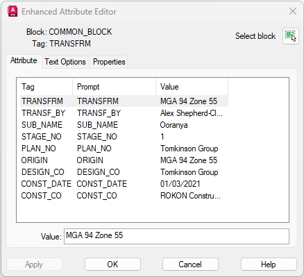 This image shows the Common Block projection MGA-55. |
| Warning: Common Block Projection does not match projection setting | This Warning is raised when the Projection in the Common Block does not match the ACDC Coordinate System is stored in the setting gProjection. | Ensure the Common Block Projection matches the Projection assigned to the gProjection setting . |
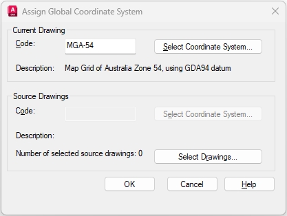
Table: List of common Warning descriptions, the cause and remedy to fix.
Common Complex Validation Warnings
| COMMON COMPLEX VALIDATION WARNINGS | ||
| Error Description | Error Cause | Error Fix |
| Warning: Primary Object (Layer/Tag Name) Value is not greater than adjacent object (Layer/Tag Name) |
RA CHECK STARTPOINT/ENDPOINT EQ/NEQ/GT/GTE/LT/LTE Checks
|
In the case of the Drainage Pipe example provided, the Downstream Pipe Invert Level [DS_IL] must be lower than the Upstream Pipe Invert Level [US_IL], based on the drainage reticulation being a gravity network. Warning: Primary Object (DSPEC_PIPES/DS_IL) Value is not greater than adjacent object (DSPEC_PIPES/US_IL). Ensure that the Invert Levels for both the Upstream and Downstream pipes have been captured correctly. |
Table: List of common Complex Warning descriptions, the cause and remedy to fix.
Compound Validations
Compound Validations allow users to configure additional attribute, spatial or a combination of attribute and spatial rule checks, based on comparisons, ranges, limits, multi value lists etc. These additional Compound Validations can be categorized into three main types:
- Compound Attribute Validations.
- Compound Spatial Validations.
- Compound Spatial/Attribute Validations.
The table WAE_ATTR_RULEMAP maps the various Compound Validations error types (WARNING or ERROR) for different rule type configurations. This table also sets the order in which the rules are applied. The rule parameters determine what criteria the rules must meet in order to pass or fail.
There are various Rule Types that can be configured as per the examples provided below:
- Compound Attribute Validations (Examples).
- FORMATSTR: Checks for a single character in a text string and if matches returns True, no match returns False.
- SUBSTR: Checks for a specific character, or string of characters in a sequence, applies the operator defined and returns a False if criteria is not met, and the Error is logged.
NOTE: See the list of permitted operators include: equal to (EQ), not equal to (NEQ), greater than (GT), less than (LT), greater than and equal to (GTE), and less than and equal to (LTE). - MVCHECK: Used for scenarios where if a pipe is captured with a certain material, then the permitted pipe diameter must match what is configured.
NOTE: Where the rule type is configured as MVCHECK, the list of configured multi value attributes are stored in the table WAE_ATT_MVRULECHECK. - COMPARECHECK: Used for scenarios where if, in the example of gravity mains, the upstream manhole invert level must be greater than the downstream invert level.
- MULTICHECK: Used for scenarios where if a Storm water manhole is captured exceeding a specific depth, there needs to be a certain number of rungs captured for access to the pipe.
- RANGEEX: Checks if a value falls within a specified minimum and maximum range of values. Exception values can also be specified.
- VALUECHECK: Checks if a number value is equal to (EQ), not equal to (NEQ), greater than (GT), less than (LT), greater than and equal to (GTE), and less than and equal to (LTE) a specified numeric value.
- Compound Spatial Validations (Examples):
- ISINSIDE: Checks to make sure there is a certain object falls within another object, for example: a Road Center-line must be captured within a Road Surface Area.
- LINKLIMIT: Checks if more than one pipe exits from a single node such as a manhole.
- NODELIMIT: Checks on a pipe with connecting valves that the minimum number of valves permitted is one and maximum is 2.
- Compound Spatial/Attribute Validations (Examples):
- RACHECK: Related Attribute checks for example: The diameter of a fitting must match the diameter of the pipe, or for a sewer manhole, the node cover level minus the node depth is equal to the outlet pipe's start invert level.
- CHECKLINK: Checks where an attribute value assigned to one object matches another object’s attribute value based on a spatial link between the two objects such as object one being INSIDE, or CROSSING the second object.
- CHECKCONNECT: Enforces the existence of an asset based on another asset, for example: A Storage Tank can only occur at the END of a stormwater pipe. This validation only works on polyline/inserts, and the Primary Object must be a polyline, i.e. the stormwater pipe.
- DISTCHECK: Checks the number of secondary objects WITHIN/MAX/MIN distance of the primary object. Used in scenarios to generate warning/error messages if a road center-line within a road polygon does not have matching road name.
NOTE: Currently, the compound validations are configured on the customer database by means of SQL scripts. It is recommended that you contact the Support Team at Open Spatial to assist with determining and configuring these validation rules.
Notes on Object Data
- Validated objects (as indicated by the ACDC_VALIDATED object data table) are not reviewed by the Validate ACDC Drawing tool on subsequent validation runs. If you need to re-validate an object, you must remove its existing object data. To remove existing object data, use the Delete Object Data Tables button . When you press this button, you are presented with two options:
- Tables: This option will remove all object data tables from all objects in the drawing. You must use this option if you have made some changes to your configuration.
- Selection: This option will remove object data tables from only the selected objects.
With object data removed, the Validate ACDC Drawing tool will view the selected objects as un-validated and will subject them to a complete validation check.
- Tables: This option will remove all object data tables from all objects in the drawing. You must use this option if you have made some changes to your configuration.
- Care must be taken when using the Delete Object Data Tables tool. If you remove object data from an object that has been split (broken) by the Validate ACDC Drawing tool, these objects will be viewed as two completely separate objects by the Validator on subsequent validation runs. The Validator will now expect both of these objects to have their own associated blocks, which will not be the case because they were a single object in the original drawing. This means that objects that have been split by the Validator and then have their object data removed will not pass subsequent validation runs. Therefore, you should not ever remove object data from objects that have been split by the Validate ACDC Drawing tool.
- The user must ensure that no forward slash character ("/"), is used in the object data field names, suggest the user uses the underscore instead ("_").
- ACDC Validator now also handles MPOLYGON object class type, where object data can be copied over to the MPOLYGON.
- The Validator now has improved performance where the selection is improved on common block entities when attaching attributes, and now only selects a block once and not every time attributes are attached to an object.
- Ability to handle MTEXT features are catered for, to prevent the user from exploding these features and losing the core benefits of formatting etc. This function now generates a line from the base-point to position 1 of the block. It also inserts a small circle at the base-point with an arrow-head on the other side of the line. This arrow-head has the capacity to resize itself based on the percentage of the line length to handle short lines more effectively. Fundamentally this functionality also allows for the incorporation into both straight lines and multi-segment lines.
- Additional Compound Validations can be configured for sewer and drainage pipes to ensure that the end invert level is not greater than the start invert level for each pipe segment. This validation assists in determining if the pipe direction, based on Start and End Invert Levels corresponds to the direction of the pipe drawn.
- Linear Direction validations can be configured for line/polyline objects, such as sewer and drainage pipes, to verify if the direction of the drawn line representing the pipe corresponds to the connectivity of the start and end nodes. Linear Direction arrows can be configured to display on the pipes in the drawing to indicate the flow direction. The size of the direction arrows is also configurable.