Conversion Process
Conversion Process for ACDC
The Conversion process is where objects within the currently open drawing are translated to the defined destination format. Only objects that have been validated will be converted.
The steps required to complete the conversion process are listed below.
- Press the Connect to Database
 button and connect to the database that contains the ACDC system tables.
 - Press the Attach GIS Layers (All Features)
 button to recreate all the target layers in the AutoCAD Task Pane. The saved FDO layers must be present in the Task Pane for the Convert tool to run. If you cannot see the AutoCAD Task Pane, type MAPWSPACE in the command line and select On.
OR
Press the Attach GIS Layers (Related Features) button to recreate the only related target layers in the AutoCAD Task Pane. The saved FDO layers must be present in the Task Pane for the Convert tool to run. If you cannot see the AutoCAD Task Pane, type MAPWSPACE in the command line and select On.
When loading the staging database via Generation of FDO layers, only tables which correspond with those present in the drawing will be queried out. This is done to prevent excessive time being lost via the querying from the staging database.
If there are no assets present within the model space, then everything will be queried out from the staging database, as this is needed during the template validation. - Press the Convert to GIS button
 to commence the conversion process.
If prompted to overwrite the external (CSV) file, select the appropriate option (Y will overwrite all data in the external file, while N will append the new information to the end of the file). The external CSV file is created if you selected to save any of your attributes to a CSV file. - Select the objects you wish to convert. You can do this by either manually selecting the objects in your drawing using the mouse, or you can simply type “all” and then press the Enter key on your keyboard to select all the objects within the drawing file.
- Press the Enter key on your keyboard, or press the right-button on your mouse to begin the conversion routine.
- If the Conversion routine has executed successfully, you will see command line status messages for successful conversion. All the validated objects within your selection will now be displayed as:
- FDO objects (for FDO users), or
- Records in a CSV file/table depending on configuration.
- You now need to commit the converted data to your destination tables. To do this, see the steps outlined in the Post FDO Features to Database section.
Post FDO Features to Database
To commit converted features to your defined destination tables follow the steps outlined below.
- Make sure the AutoCAD Task Pane is turned on. To turn the Task Pane on type MAPWSPACE in the command line, and select On.
- On the ACDC ribbon bar select Check in Features in the FDO menu. This will save all the converted features on all layers to the defined destination table.
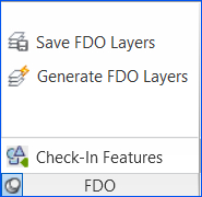
Fig: Check in Feature Menu Item - If any errors occur during the data transfer, the affected destination layer will have a warning graphic displayed against it. If you do not see a warning graphic, the Check in Features process has completed successfully.
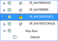
Fig: Layer Warning Graphic - If errors have occurred, click the AutoCAD warning message button
 to review the error log. Address the listed errors as required and re-convert the data for the affected destination layer.

Fig: Review Error Log - Once the Check in Features tool executes without producing any errors (i.e. there are no warning graphics displayed against the selected destination layer), the Conversion process is complete for that destination layer.
Repeat this process for each of the destination layers with errors in the AutoCAD Task Pane.
Conversion Process for ACDC with Munsys
The Conversion process is where objects within the currently open drawing are translated to the defined destination format. Only objects that have been validated will be converted.
The steps required to complete the conversion process are listed below.
- Press the Connect to Database
 button and connect to the database that contains the ACDC system tables.
 - Press the Convert to GIS
 button to to commence the conversion process.
At this stage you may be presented with a Connect to Database dialog. This connection dialog refers to your Munsys database, not the ACDC database.
Enter your Munsys login credentials and press the OK button.
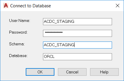
Fig: Munsys Connection Dialog BoxIf prompted to overwrite the conversion report file, select the appropriate option (Y will overwrite all data in the report file, while N will add the new information to the end of the file).
If prompted to overwrite the external (CSV) file, select the appropriate option (‘Y’ will overwrite all data in the external file, while ‘N’ will add the new information to the end of the file). The external CSV file is created if you selected to save any of your attributes to a CSV file.
- Select the objects you wish to convert. You can do this by either manually selecting the objects in your drawing using the mouse, or you can simply type All and then press the Enter key on your keyboard to select all the objects within the drawing file.
- Press the Enter key on your keyboard, or press the right-button on your mouse to begin the conversion routine.
- If the Conversion routine has executed successfully, you will see command line status messages for successful conversion. All the validated objects within your selection will now be displayed as:
- Munsys objects, or
- Records in a CSV file/table depending on configuration.
- You now need to commit the converted data to your destination tables. To do this, see the steps outlined in the Post Munsys Features to Database section below.
Post Munsys Features to Database
To post converted features to your Munsys database, follow the steps outlined below.
- Press the Post to Database button
 , located on the Munsys Integrity toolbar.
 - If there are data compatibility issues between the converted features and the destination Munsys database, you will be presented with an Object Integrity Errors prompt. Press the Errors... button on this dialog to view the details of the errors. You must address and correct all of these issues before the data will post successfully to the database.
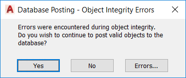
Fig: Object Integrity Error Dialog Box
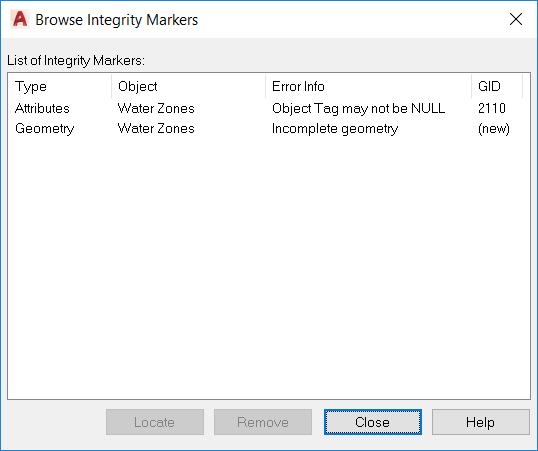
Fig: Browse Integrity Markers Dialog Box